

Quadcept : Environment Settings
Draw (PCB)
Configure the drawing display and operation settings for the design work area when creating PCBs.
For more details about how to display the setting screen for Environment Settings, refer to About Environment Settings.
Draw (PCB) Screen
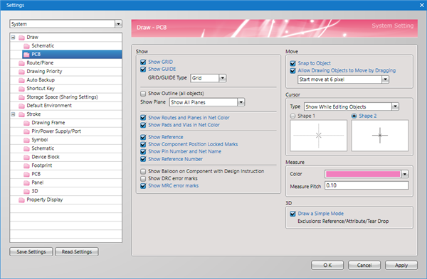
Display
Configure settings related to the display.
| Item | Description | ||||
|
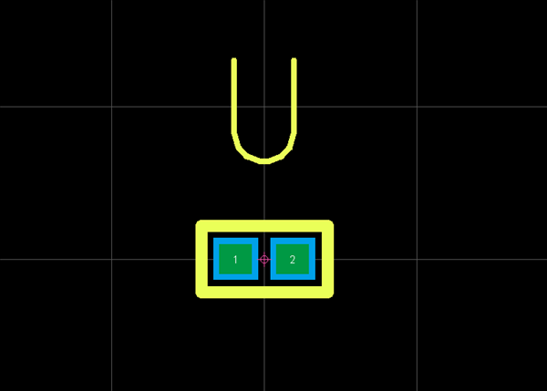
Show GRID |
Toggles GRID lines ON/OFF. |
||||
|
Show GUIDE |
Toggles GUIDE lines ON/OFF. |
||||
|
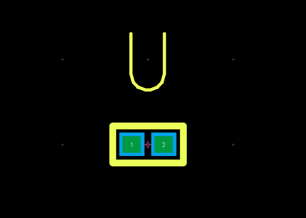
GRID/GUIDE Type |
For GRID display, you can select "Grid" or "Dot".
|
||||
|
Show Outline (all objects) |
An outline of all objects is shown. |
||||
|
Show Plane |
For Show Plane, you can select "Show All Planes", "Show Static Planes only", or "Show Outline only". |
||||
|
Show Routes and Planes in Net Color |
Configures settings for whether the Net Color will be applied to routes and planes when a Net Color is specified. |
||||
|
Show Pads and Vias in Net Color |
Configures settings for whether the Net Color will be applied to pads and vias when a Net Color is specified. |
||||
|
Show Reference |
You can toggle Show Reference ON/OFF. |
||||
| Show Component Position Locked Marks | Toggles visibility of locked marks when component position is locked. You can toggle this using Toggle Visibility of Component Position Locked Marks. |
||||
|
Show Pin Number and Net Name |
You can display the Pin Number and Net Name in Pads and the Net Name in Vias. |
||||
|
Show Reference Number |
You can select whether to show the Reference Number in the center of components/footprints. |
||||
|
Show Balloon on Component with Design Instruction |
Balloon display is done for components where PCB Design Instructions are performed. |
||||
|
Show DRC error marks |
You can select whether to show DRC error marks. |
||||
|
Show MRC error marks |
You can select whether to show MRC error marks. |
Move
Configure settings related to the display.
| Item | Description |
|
Snap to Object |
Configures settings for whether to perform snap even when an Object or Pin Point is not placed on the GUIDE line. |
|
Allow Drawing Objects to Move by Dragging |
Configures settings for Allow Drawing Objects to Move by Dragging. |
Cursor
Configure settings related to mouse cursor display.
| Item | Description | ||||
|
Type |
You can select [Show While Editing Objects] or [Show Always]. |
||||
|
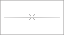
Shape |
Select a mouse cursor shape.
|
Measure
Configure settings related to the Measure function.
| Item | Description |
|
Color |
Sets the Measure function color. |
|
Measure Pitch |
Sets the Measure Memory Measure Pitch. |
3D
Configure settings related to 3D display.
| Item | Description |
|
Draw a Simple Mode |
By placing a check, Reference, Attribute, Tear Drop, etc., will not be shown in 3D. |