Next, draw a Board Outline shape. With Quadcept, things placed on the "Board" layer in "Other" are recognized as Board Outline lines.
Keep in mind that Board Outline lines are needed for various export data such as 3D data (IDF, STEP), DSN, and ODB++, so it must be a closed figure.
By importing DXF files and IDF files that are exported from a mechanical system CAD (3DCAD), etc., it can also be used as Board Outline line.
There are the following three methods for drawing Board Outlines.
Drawing a Board Outline
Reading a Board Outline Using DXF/DWG Data
Reading a Board Outline Using IDF Data
About the mounting hole creation method, refer to the following.
Placing a Mounting Hole
Drawing a Board Outline
This is the method for drawing a Board Outline using "Lines", "Rectangles", "Circles", "Arcs", etc.
| (1) |
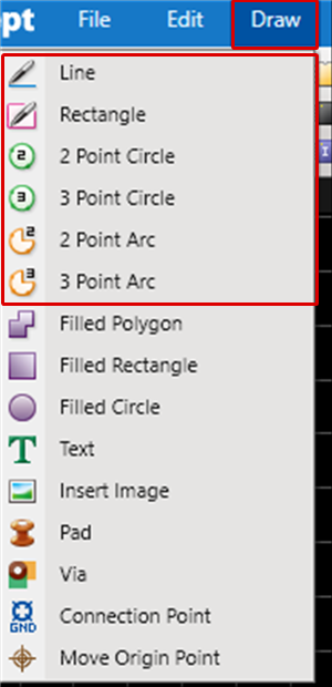
Select [Draw]
=> [Line], [Rectangle], [Circle], or [Arc].
* For more details about the Draw function, refer to About Drawing and Editing.
|
|
 |
| (2) |
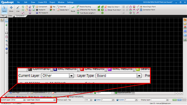
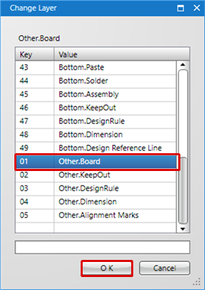
Set Current Layer to "Other", and Layer Type to "Board". |
|
 |
| |
(* Or, press the "L" key, select "Other.Board" from the Change Layer screen, and then click the "OK" button) |
|
 |
| (3) |
Draw the Board Outline shape. |
|
 |
Reading a Board Outline Using DXF/DWG Data
This is the Board Outline method by reading Board Outlines designed with a mechanical system CAD (3DCAD), etc., using DXF data or DXG data.
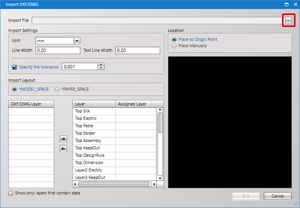
| (1) |
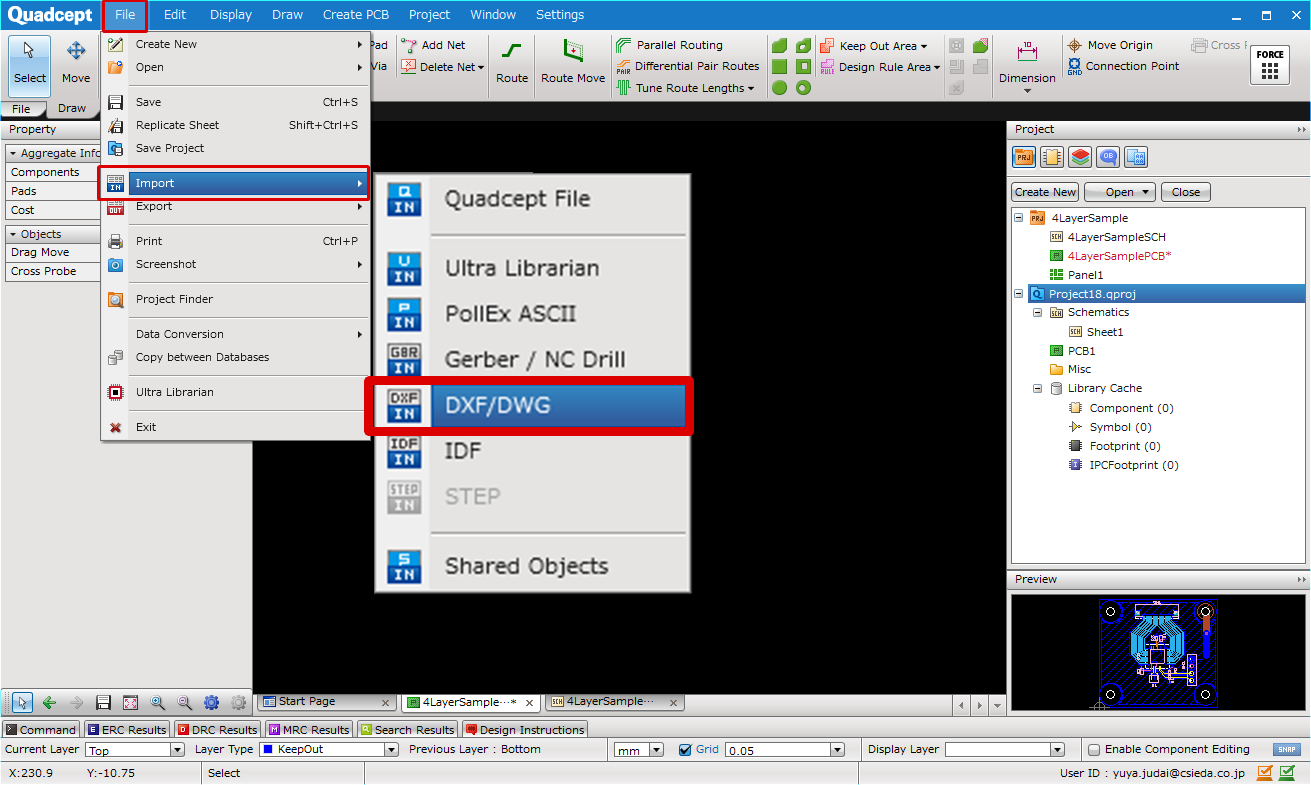
[File]
=> [Import]
=> [DXF/DWG].
=> The " DXF/DWG" screen will open. |
|
 |
| (2) |
Click "..." next to Import File => The "Open" screen will appear. |
|
 |
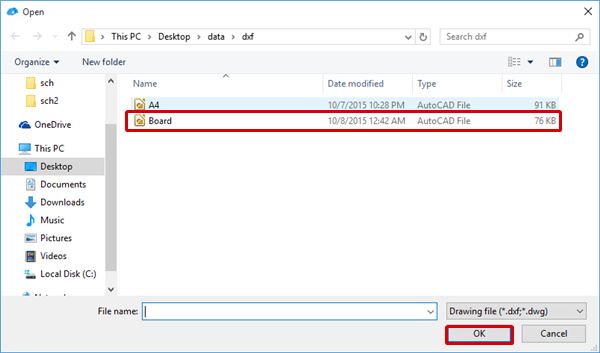
| (3) |
Select a DXF file. |
| (4) |
Click "OK". |
|
 |
| (5) |
From the DXF layer, select "Other:Board" as the Board Outline layer. |
| (6) |
Click the "=>" button. |
| (7) |
Click "OK". |
|
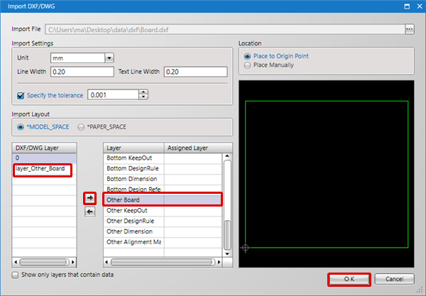 |
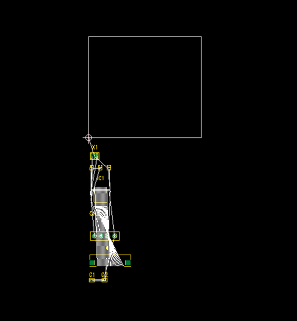
| |
The DXF data will be read as the Board Outline. |
|
 |
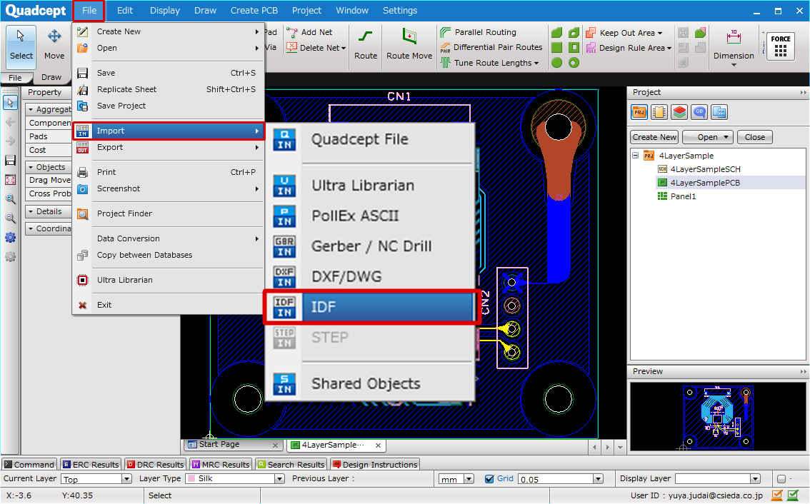
Reading a Board Outline Using IDF Data
This is the Board Outline method by reading Board outlines designed with a mechanical system CAD (3DCAD), etc., using IDF data.
| (1) |
[File]
=> [Import]
=> [Import IDF].
=> The "Import IDF" screen will open. |
|
 |
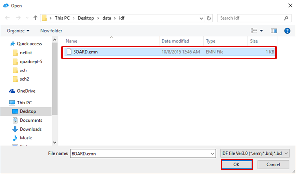
| (2) |
Select an IDF file. |
| (3) |
Click "OK". |
|
 |
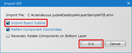
| (4) |
Place a check for "Import Board Outline". |
| (5) |
Click "OK". |
|
 |
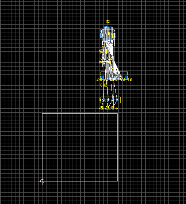
| |
The IDF data will be read as the Board Outline. |
|
 |
The following will explain how to draw mounting holes (holes on printed boards for affixing the printed board to devices, etc., and for mounting large components to the printed board).
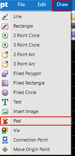
Mounting holes are created using "Pad". |
| (1) |
Select [Draw]
=> [Pad]. |
|
 |
| (2) |
Configure settings and then click "OK".
* If necessary, set
"Electric"/"Solder".
************
From the Drill Settings,
configure settings for the hole Shape, Hole Diameter,
and whether to have Plating.
|
|
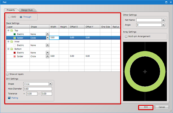 |
| (3) |
To place the Pad, click the coordinate where you want to place it. |
|
 |
| |
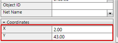
* After placing, the Coordinates can be adjusted. |
| (1) |
Select. |
| (2) |
From the Property Window, adjust the Coordinates. |
|
 |

