

PCB Layout CAD : DRC/MRC Settings
Dynamic Plane Connection
By drawing a Dynamic Plane, it is possible to configure the Connection Width, number of Thermal Connections, and Clearance settings for each Net, and automatically change the shape.
All can be set as a batch, and you can adjust the shape for each Pad later.
By using a Dynamic Plane, you can minimize Plane Layer return work.
When executing a Dynamic Plane, there is also a Delete Unconnected Plane function available.
For more details about opening the DRC/MRC Settings screen, refer to About DRC/MRC Settings.
Plane Settings
Setting Method
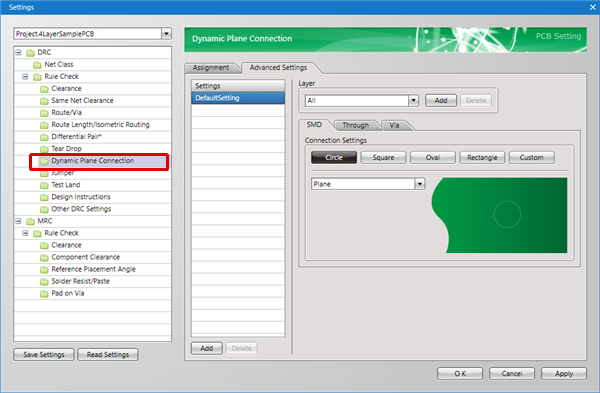
First, in Settings, there is an "Assignment" tab and "Advanced Settings" tab.
The "Advanced Settings" tab is used for configuring actual settings, and the "Assignment" tab is used for configuring which settings are assigned to which Net.
About the Work Procedure
STEP 1: Create a Net Class from the "Net Class" tab
STEP 2: Configure settings in the "Advanced Settings" tab
STEP 3: Assign settings to the Net Class in the "Assignment" tab
The following will explain each setting tab.
Explanation of Each Setting Tab
| Tab Name | Content |
|
It is possible to assign the "Settings" that are applied to Nets set in the "Net Class". For example, you can create a "Power Supply Net Class (GND, VCC)" Net Class, and assign the setting for "Power Supply Net Settings". |
|
|
Configures actual settings. |
Advanced Settings
For more details about adding settings, refer to Adding Settings.
Connection Settings

For objects for which the connection shape applies, there are three types; "Pad", "SMD", and "Via".
| Item | Content |
|
Pad |
Configures Tear Drop Settings for Dip Pads. |
|
SMD |
Configures Tear Drop Settings for CHIP Pads (Pads without Drills). |
|
Via |
Configures Tear Drop Settings for Vias. |
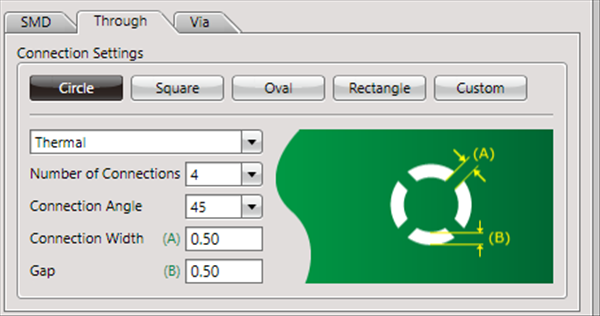
It is possible to set the connection method for each shape.
| Round | Square | Oblong | Rectangle |
|
|
|
|
|
| Thermal | Plane | No Connection | |
| Shapes with slits for improving heat dissipation | Shapes that connect without Clearance | Shapes with Clearance | |
|
|
|
|


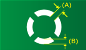
Thermal" Settings
| Item | Content | ||||
|
Number of Connections |
Configures the number of Thermal Spokes. |
||||
|
Connection Angle |
The Thermal Spoke position can be changed by selecting from "90 degrees" and "45 degrees".
|
||||
|
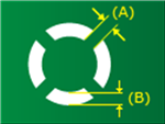
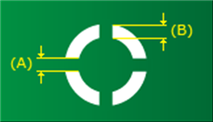
Connection Width (A) |
Configures the Thermal Spoke Width. |
||||
|
Gap (B) |
Configures the Clearance Width (Gap) from the Pad Land to the Plane. |
No Connection" Settings
| Item | Content |
| Clearance |
Configures the Clearance Width from the Pad or Land to the Plane. |
Layer Settings
For more details, refer to Layer Settings.
Assignment Settings
For more details, refer to Assignment Settings.