

PCB Layout CAD : Create Plane
Drawing Planes
This page describes how to draw various planes.
For how to toggle plane types, refer to here.
Drawing Various Planes
There are three kinds of plane objects, "Polygon Plane", "Rectangle Plane" and "Circle Plane". The method for drawing each object is as follows.
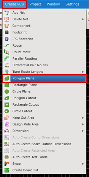
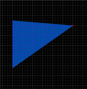
Drawing Polygon Plane
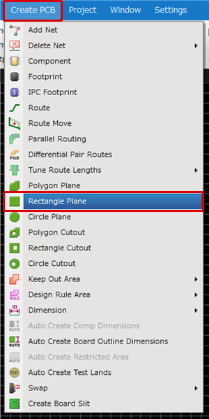
Drawing Rectangle Plane
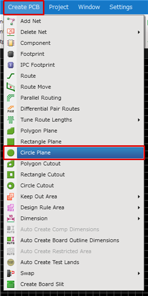
Drawing Circle Plane
| Drawing Polygon Plane |
| The following explains how to draw a polygon plane. |
|
|
|
|

|
|
|
 |
|
 |
|
 |
|
 |
| Drawing Rectangle Plane |
| The following explains how to draw a rectangle plane. |
|
|
|
|
|
|
|
 |
|
|
|
|
|
 |
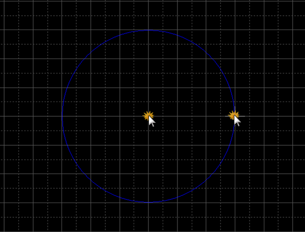
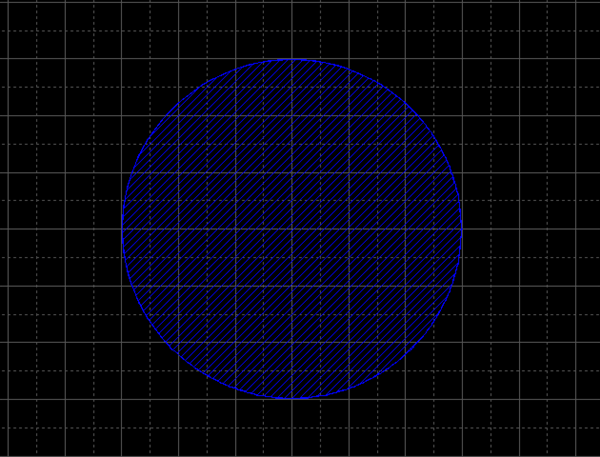
| Drawing Circle Plane |
| The following explains how to draw a circle plane. |
|
|
|
|

|
|
|
 |
|
|
|
|
|
 |
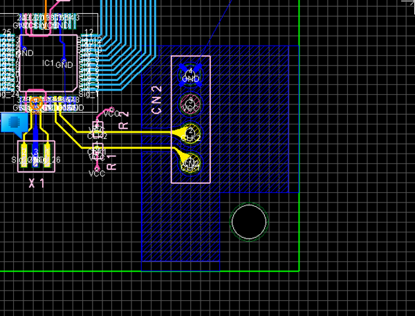
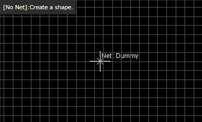
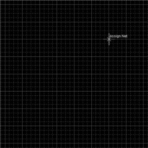
Drawing Planes Without Net
When creating a plane, you can draw a plane without a net by drawing it with the "Ctrl" key held down.
| Plane Creation without a Ctrl key | Plane Creation with a Ctrl key |
|
|
|

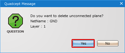
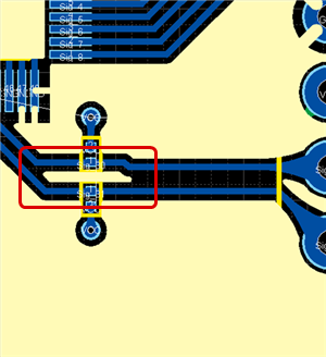
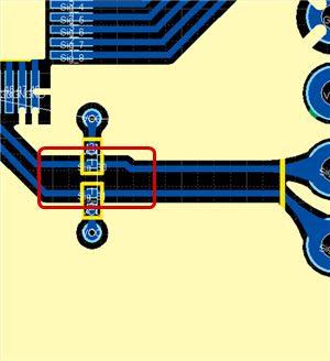
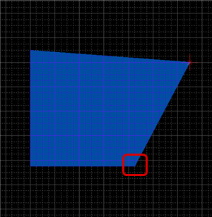
Deleting Unconnected Planes
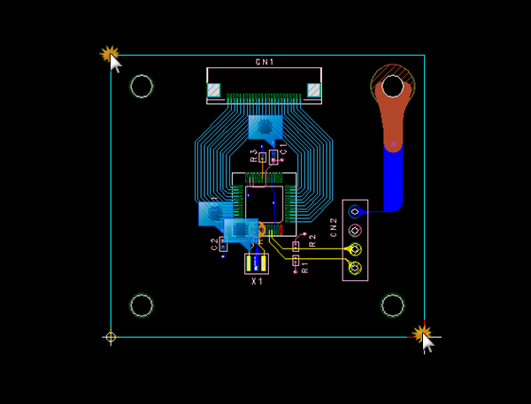
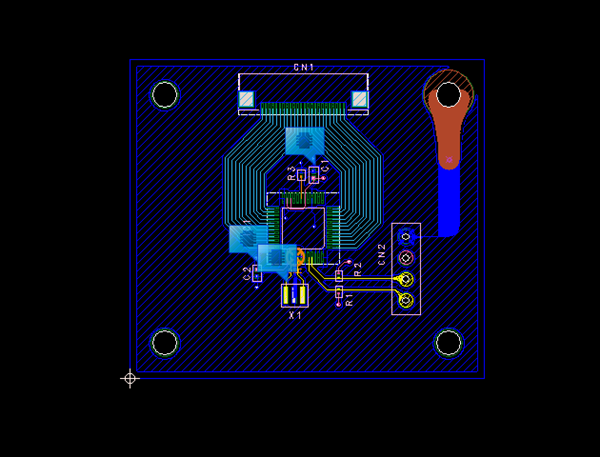
Unconnected Planes are planes that become "Electrically Unconnected" due to the Plane Line Width when a plane is generated. When there is an Unconnected Plane, a problem may occur due to nearby pattern characteristics, or the appearance may not be good. Quadcept's Dynamic Planes have a function for deleting Unconnected Planes automatically when rebuilding a plane.
| With Unconnected Planes | After Deleting Unconnected Planes |
|
|
|
Various Operations for Drawing Planes
The following will explain each operation for drawing a plane.
Changing the Corner Angle
Switching the Angle
Pushback Plane
Changing the Corner Shape
Canceling a Plane
Exiting Create Plane Mode
Changing the Corner Angle
This is a function for changing the Corner of drawn planes between 45 degrees, 90 degrees, and Free.
The following is an example of changing the bending angle for route corners.
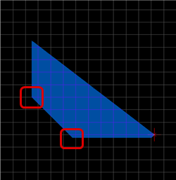
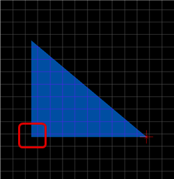
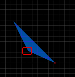
Plane Corner Bending Angle
| 45 degrees | 90 degrees | Free |
|
|
|
|
The following is the operation for changing the plane corner bending angle.
Method 1: [Keyboard] => Press "S"
Method 2: [Right Click] Select => [Change the Bending Angle]
Method 3: From the Property Window, change the "Bending Angle"
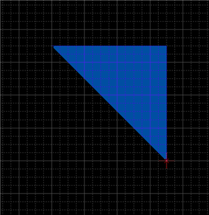
Switching the Angle
| Before Switching | After Switching |
|
|
|
The following is the operation for switching the angle.
Method 1: Right click, Select => [Switch Angle]
Method 2: Press "X" on the keyboard
* It can also be confirmed and changed from the Property Window.
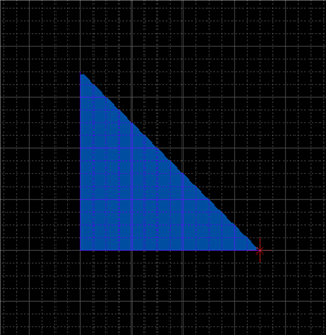
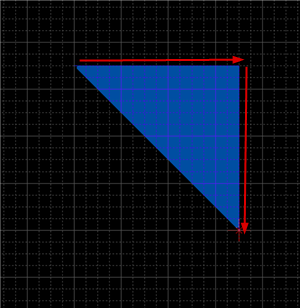
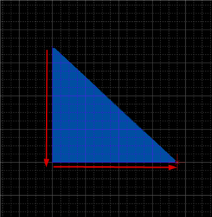
It is also possible to determine the pulling direction by tracking using the mouse pulling direction.
| When pulling to the right side first | When pulling to the bottom first |
|
|
|
Changing the Current Layer
The following is the method for changing the Current Layer while drawing a plane.
- Changing from the Change Current Layer Menu
- Changing from the Status Bar
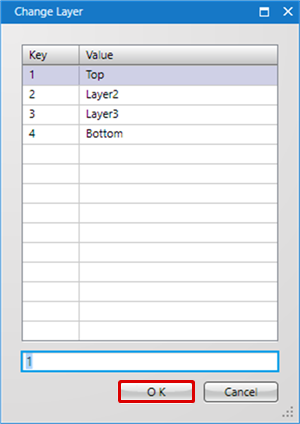
| Changing from the Change Current Layer Menu |
| This is the method for instantly switching the Current Layer using the Shortcut Key. |
|
 |
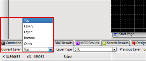
| Changing from the Status Bar |
| This is the method for switching from the Current Layer displayed in the Status Bar. |
|
 |
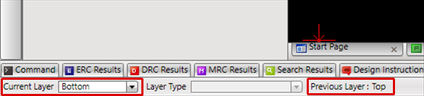
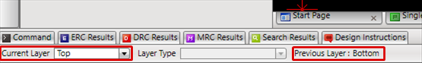
Changing to the Previous Layer
This is the method for switching to the "Previous Layer". It is possible to toggle between frequently used layers.
| Changing to the Previous Layer |
| It is possible to toggle between frequently used layers. |
|
 |
|
 |
Pushback Plane Corner
When creating a plane, you can return the corner to the previous status.
| Before Pushback | After Pushback |
|
|
|

The following is the operation for executing pushback.
Method 1: Right click, Select => [Pushback]
Method 2: Press "Back" on the keyboard
Changing the Corner Shape
The Corner Shape can be toggled between "Line (Angle)" and "Arc", and when the Corner Shape is "Arc", the Arc Length can be easily adjusted.
For more details, refer to Toggling the Corner Shape.
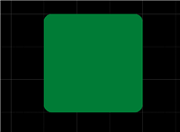
| Corner Shape (Line) | Corner Shape (Arc) |
|
|
|
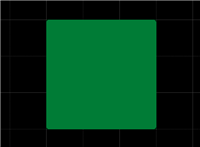
Even when the corner shape is set to Line, the Outline Width will be round.
Canceling a Plane
When creating a plane, it is possible to return to the status before drawing by canceling the route being created.
| Before Canceling | After Canceling |
|
|
|
The following is the operation for executing pushback.
Method 1: Right click, Select => [Cancel]
Method 2: Press "Escape" on the keyboard
Exiting Create Plane Mode
The following is the operation for exiting Create Plane Mode.
When not creating a plane,
Method 1: Right click, Select => [Cancel]
Method 2: Press "Escape" on the keyboard