

Schematic Capture : Wiring and Editing
Parallel Wire
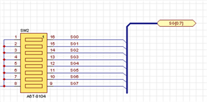
Parallel Wire is an operation for grouped wiring from pins that are placed parallel to each other.
When connecting a connector, IC, FPGA, etc., to a bus, it is not necessary to connect each wire one at a time, which allows wiring to be done quickly.
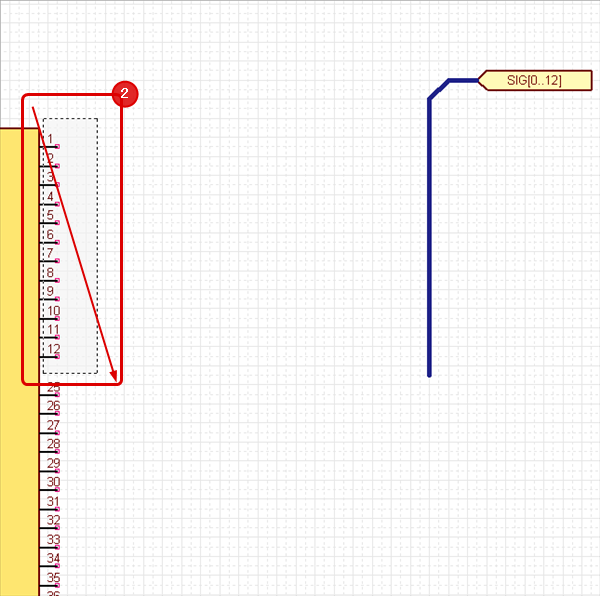
Parallel Wire Example
* For those who want to view the video in a larger screen setting: https://youtu.be/YaUe0fOIpUs
| Parallel Wire |
| The following is the operation for Parallel Wire. |
|
|
|
 |
|
 |
|
 |
Each Operation for Drawing Parallel Wires
The following will explain each operation for drawing parallel wires.
Selecting the Parallel Wire Menu
Canceling a Parallel Wire
Exiting Parallel Wire Mode
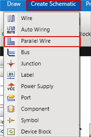
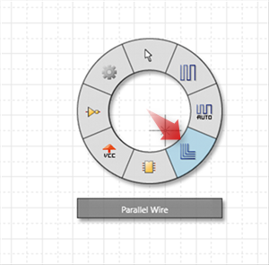
Selecting the Parallel Wire Menu
Select [Create Schematic] => [Parallel Wire]
There are several other ways to perform this. Refer to About Executing Menus.
Canceling a Parallel Wire
When creating parallel wires, it is possible to return to the status before drawing by canceling the parallel wires being created.
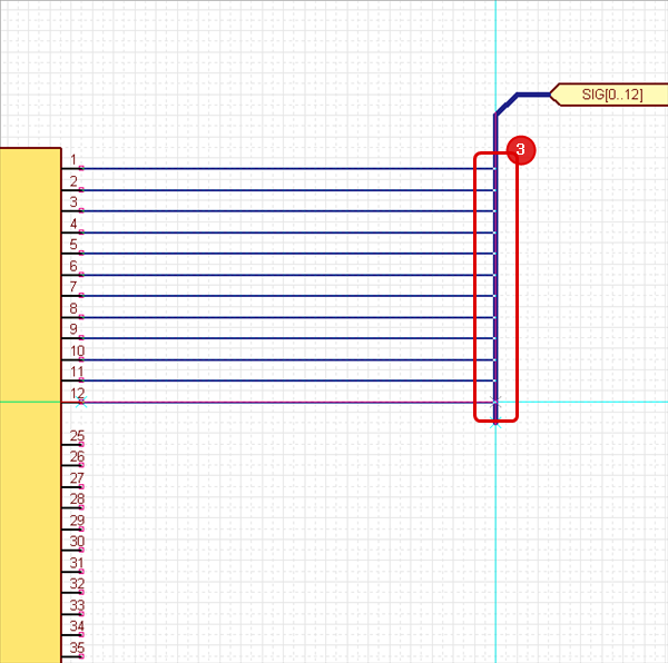
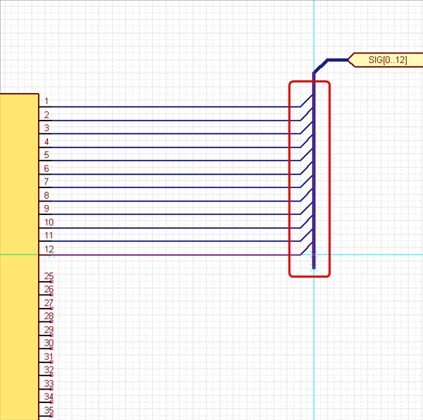
| Before Canceling | After Canceling |
|
|
 |
The following is the operation for executing pushback.
Right click, Select => [Cancel]
* Press "Escape" on the keyboard
Exiting Parallel Wire Mode
The following is the operation for exiting Parallel Wire mode.
When not creating parallel wires,
Right click, Select => [Cancel]
* Press "Escape" on the keyboard