

PCB Layout CAD : Placing Components
Align Footprint
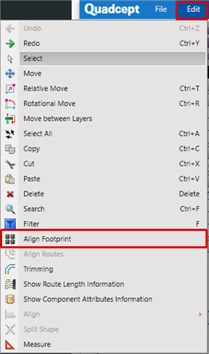
Align Footprint is a function for aligning Footprints outside the Board Outline according to Components so that they are easy to place.
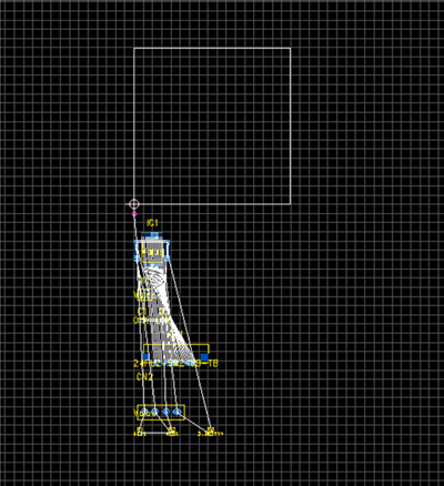
Because it is possible to execute Align Selected Components only, by aligning before placing components, it is possible to reduce the work time needed for placement.
Align Footprint Example
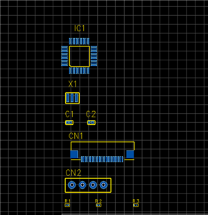
| Align Footprint |
| This is a function for aligning Footprints outside the Board Outline according to Components so that they are easy to place. |
|
 |
|
 |
|
 |
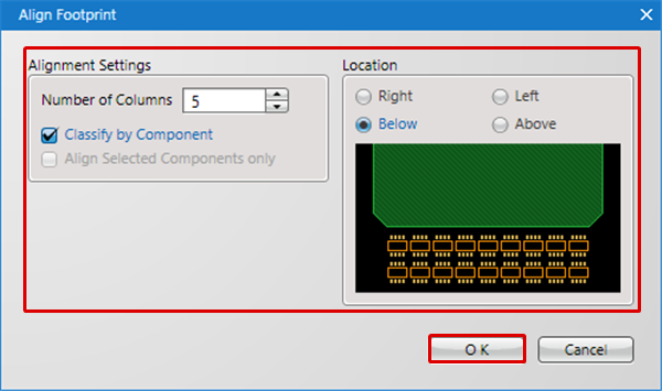
Explanation of the Align Footprint Screen
Align Footprint Screen
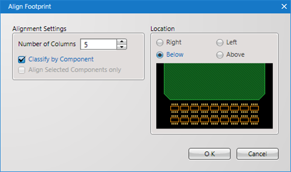
| Item | Content |
|
Number of Columns |
Specifies the number of columns for components. |
|
Classify by Component |
Specifies whether to change the Row according to the Component Name. |
|
Align Selected Components only |
When there is a Selected Component, it is possible to select whether only the selected component is the target for alignment. |
|
Location |
It is possible to specify where to align outside the Board Outline. |