

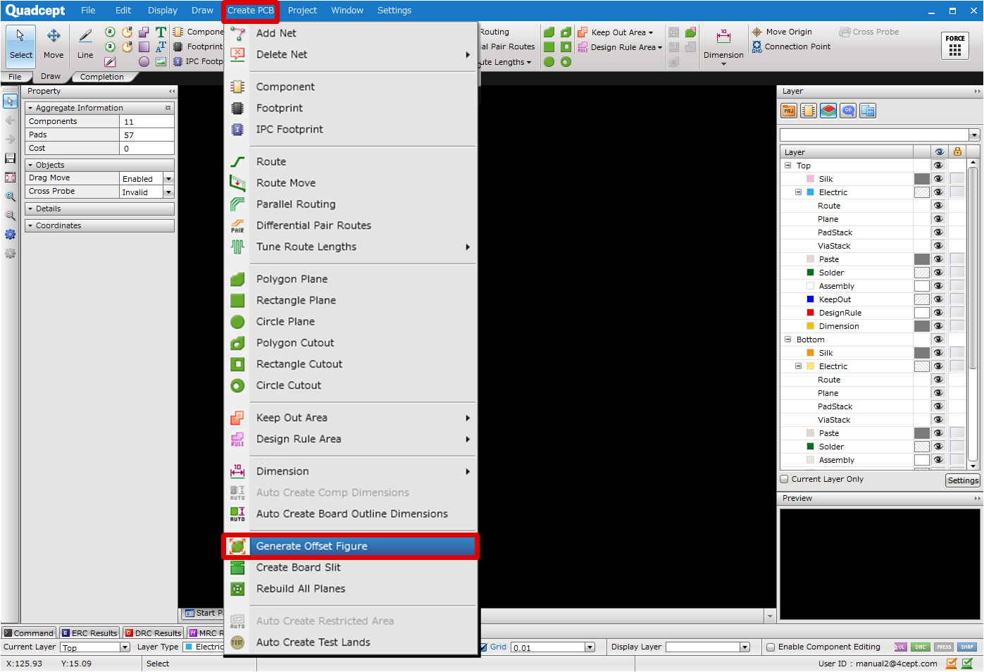
PCB Layout CAD : Various Convenient Functions
Generating Offset Figures
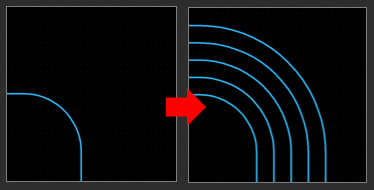
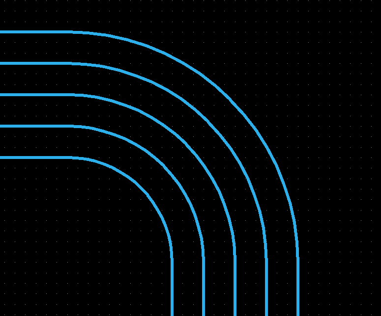
The Generate Offset Figure command is used to generate one or more objects at the location away from a currently selected object by a specified distance. This is available in PCB/Panel/Footprint sheets, and is useful when you wish to create a keep out area based on a mounting hole, or when you want to temporarily create routes at regular intervals to check the routing space.
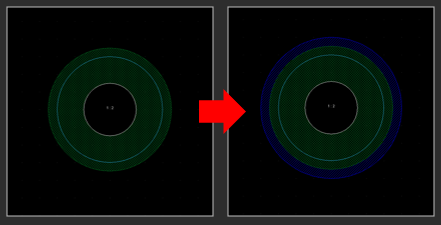
| Generating concentric routes with a certain clearance | Generating a keep out area based on a mounting hole |
|
|
|
Available Objects
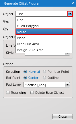
This command can generate the following objects based on a selected object.
Line / Filled Polygon / Route / Plane(Static) / Keep Out Area / Design Rule Area
When copying an arc line, Relative Move will move its origin point as well, but Generate Offset Figure will generate the object concentrically without moving its origin point.
| Relative Move | Generate Offset Figure |
|
|
|
Generating Offset Figures
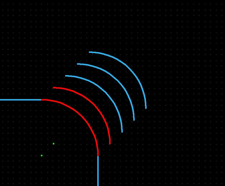
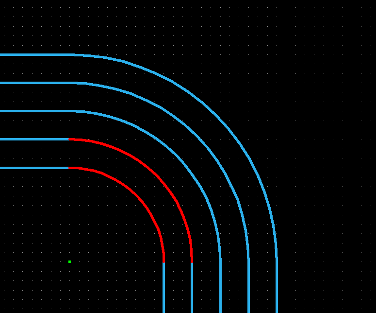
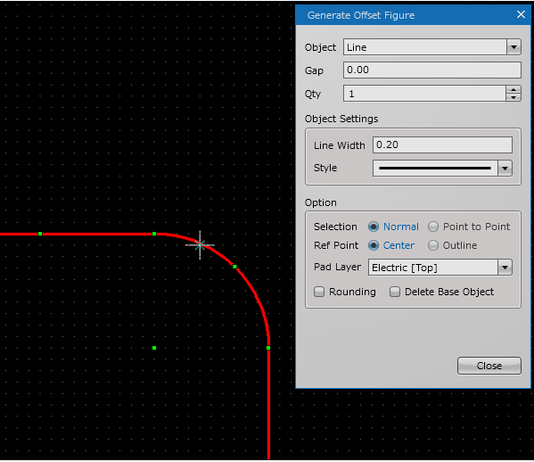
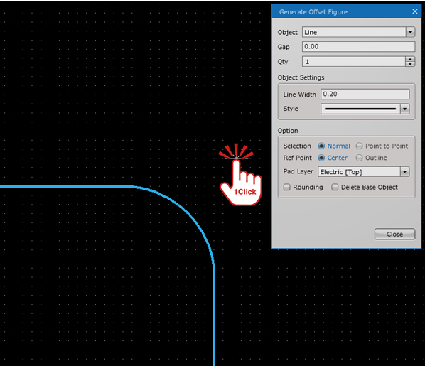
| Generating Offset Figures (Object : Route) |
| The following explains how to generate arc routes with Generate Offset Figure. |
|
 |
|
 |
|
 |
|
 |
|
|
||||
|
|
||||
|
 |

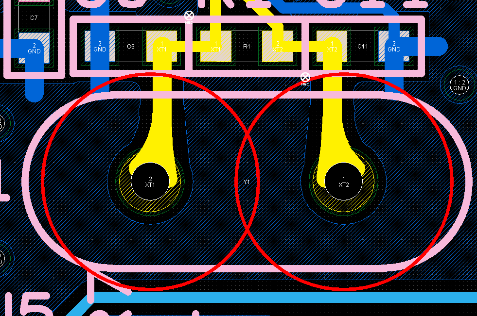
| Usage Example (Object : Keep Out Area) |
| The following explains how to generate a keep out area based on a mounting hole (through pad). |
|
|
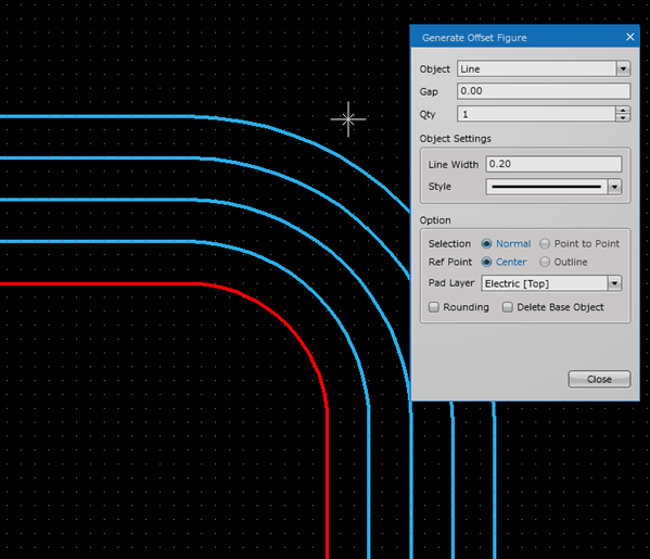
| Usage Example (Object : Line) |
| The following explains how to generate a line based on a pad land as the indication of clearance for pads. |
|
 |
Generate Offset Figure Settings
The settings consist of Common Settings and Option Settings that are shared settings, and Object Settings that vary depending on each object.
Common Settings
Object Settings
Option
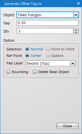
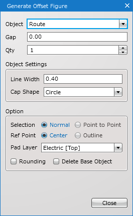
| Line | Filled Polygon | Route |
|
|
|
|
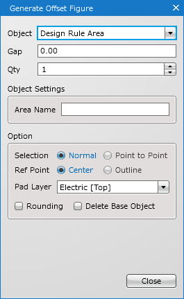
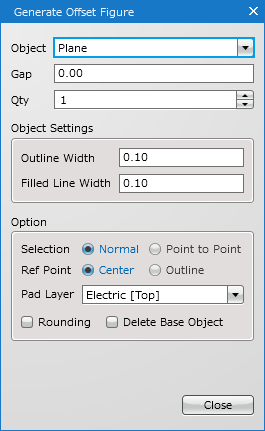
| Plane(Static) | Keep Out Area | Design Rule Area |
|
|
|
 |
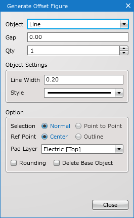
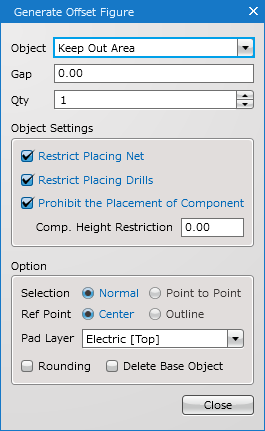
Common Settings
| Item | Description |
|
Object |
Select an object type to generate from Line, Filled Polygon, Route, Plane(Static), Keep Out Area, or Design Rule Area. |
|
Gap |
Specify the distance to generate an offset object. |
|
Qty |
Specify the number of objects to generate. |
Object Settings
The contents of object settings vary depending on each object.
| Item | Description |
|
Line Width |
Specify a line width. |
|
Style |
Select a line style from Solid Line, Dashed Line, Dotted Line, Chained Line or Chain Double-Dashed Line. |
For how to draw or edit lines, see here.
There are no object settings for filled polygons.
For how to draw or edit filled polygons, see here(Filled Polygon/Filled Rectangle/Filled Circle).
| Item | Description |
|
Line Width |
Specify a line width. |
|
Cap Shape |
Select a cap shape for a route from Circle or Square. |
For how to draw or edit routes, see here.
The net name of a generated route will be "DummyNet". "DummyNet" is a net name temporarily assigned to a route created by Generate Offset Figure. After you have created it, specify a new name as necessary.
| Item | Description |
|
Outline Width |
Specify an outline width for a plane. |
|
Filled Line Width |
Specify a line width for filling a plane. |
For how to draw or edit planes, see here.
Specify a value equal to or less than Outline Width for Filled Line Width.
| Item | Description |
|
Restrict Placing Net |
Enables to verify the existence of a net object in the area by DRC. If you wish to specify a specific net as a permitted net, change the setting after creating a keep out area. |
|
Restrict Placing Drills |
Enables to verify the existence of a drill in the area by DRC. |
|
Prohibit the Placement of Component |
Enables to verify the existence of a component in the area by DRC. |
|
Comp. Height Restriction |
Enables to verify the existence of a component that is higher than a specified height by DRC. |
For how to draw or edit keep out areas, see here.
| Item | Description |
|
Area Name |
Specify a name for a design rule area. |
For how to draw or edit design rule areas, see here.
The settings for a design rule area can be configured in the DRC/MRC Settings.
Option
| Item | Description |
|
Selection |
Select a selection method from Normal or Point to Point. Normal: |
|
Ref Point |
Select a reference point from Center or Outline. Center: |
|
Pad Layer |
Select a pad layer as a base object for generating an offset object. |
|
Rounding |
Enables to generate an object with round corners. |
|
Delete Base Object |
Enables to delete selected base object(s) when generating an offset object. This option is only available when Normal is selected as a selection method. Pads/Vias are not subject to deletion. |