Next is routing work. Draw Routes based on Net Information.
The following will explain how to draw routes and various operations when routing.
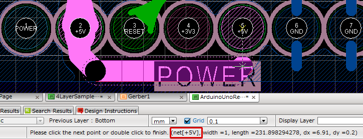
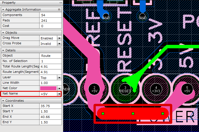
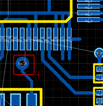
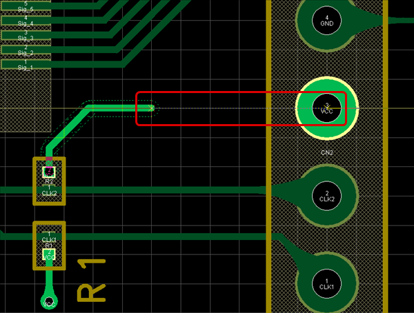
The net name is referable in the status bar at the bottom of the design screen while routing signals. After creating routes, you can see the net name in the Property Window by selecting the route.
| While Routing |
After Routing |
|
|
 |
| The following will explain drawing work for routes. |
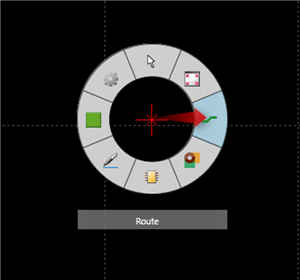
| (1) |
Click the mouse scroll button. |
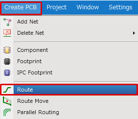
| (2) |
Select "Route".
* Same as [Create PCB]
=> [Route]. |
|
  |
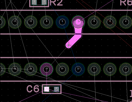
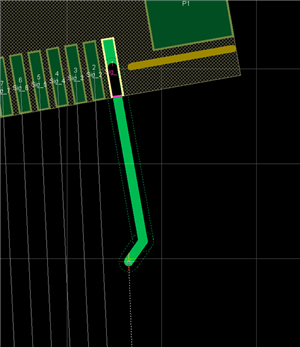
| (3) |
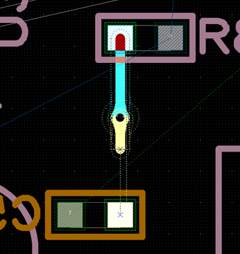
On the design drawing, click a Rats, a Route with Net Information, Via, or Pad, and then start to draw a route. |
|
 |
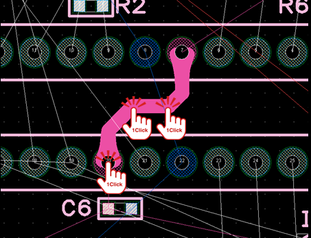
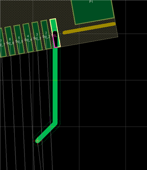
| (4) |
Click each configuration point to draw the route. The route can be finished by clicking on a Pad, etc., or by double clicking. |
|
 |
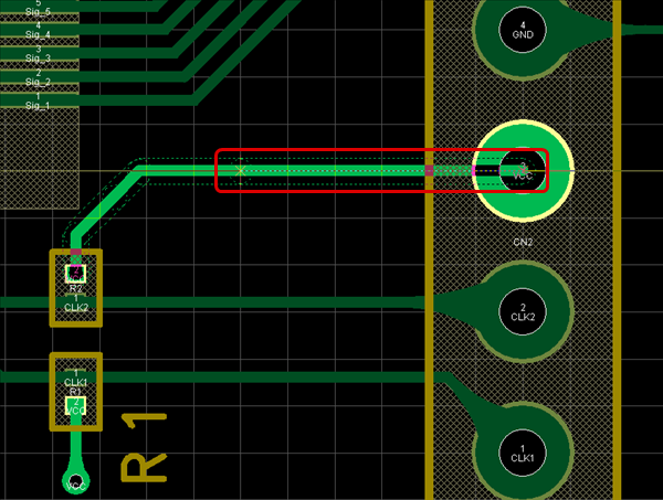
To end at the middle of a route (route pending), you can end by double clicking.
This can also be done using Fix Creating Routes and Fix Creating Routes with Via, etc.
Changing the Current Layer
When the Current Layer is changed during routing, a Via is generated automatically.
The following are methods for changing the Current Layer.
- Changing from the Change Current Layer Menu
- Changing from the Status Bar
| This is the method for instantly switching the Current Layer using the Shortcut Key. |
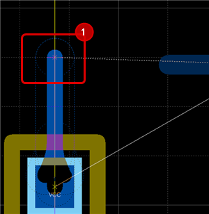
| (1) |
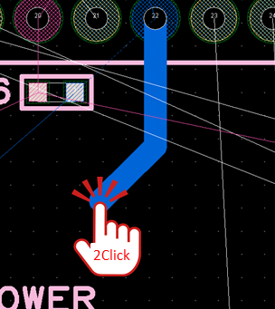
Click on the location where you want to place a Via while routing. |
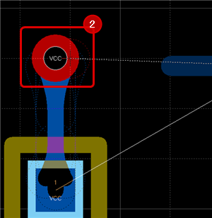
| (2) |
Press the "L" key.
(Or,
Right Click
Select => [Change Layer]). |
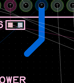
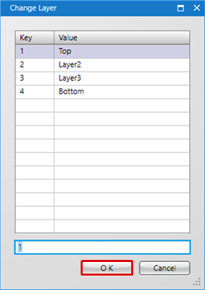
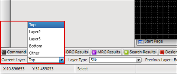
| (3) |
Select the Layer that you want to switch, and then click "OK". |
| |
Or, use "L" "4" "Enter" to switch to the "Bottom" layer.
* You can switch to the "Top" layer by pressing the Shortcuts "L"/"T", and switch to "Bottom" Layer by pressing "L"/"B". |
| |
|
|
 |
|
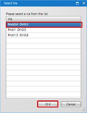
(4)
|
Select the Via that you want to use from the list, and then click "OK". |
| |
If Change Layer was done using the "L" key, you can select a Via from the list of Available Vias in the Move Layer. |
|
 |
Changing the Current Layer
| This is the method for switching from the Current Layer displayed in the Status Bar. |
| (1) |
Change the Current Layer in the Status Bar. |
|
 |
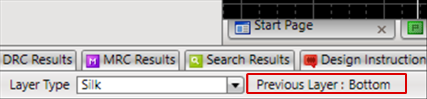
Changing to the Previous Layer
This is the method for switching to the "Previous Layer". It is possible to toggle between frequently used layers such as when performing routing of the Top surface and L1 layer.
| It is possible to toggle between frequently used layers. |
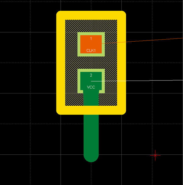
| (1) |
Click the route at the location where you want to place the Via. |
|
 |
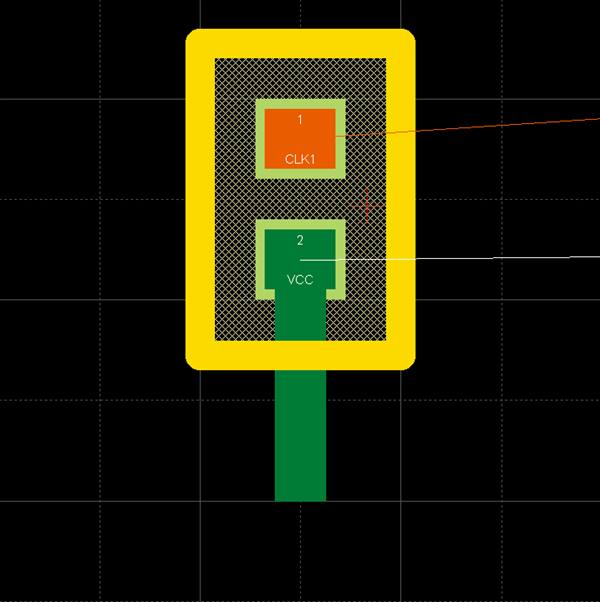
| (2) |
Press the "Tab" key.
(Or,
Right Click
Select => [Move to Previous Layer]). |
|
 |
| |
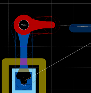
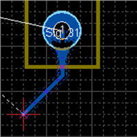
The Route Layer switches, and you can continue routing. |
| |
* When moving to the "Previous Layer", it places the Via that was used the previous time for this layer.
|
|
 |
| |
* The Previous Layer can be confirmed from the Status Bar. |
|
 |
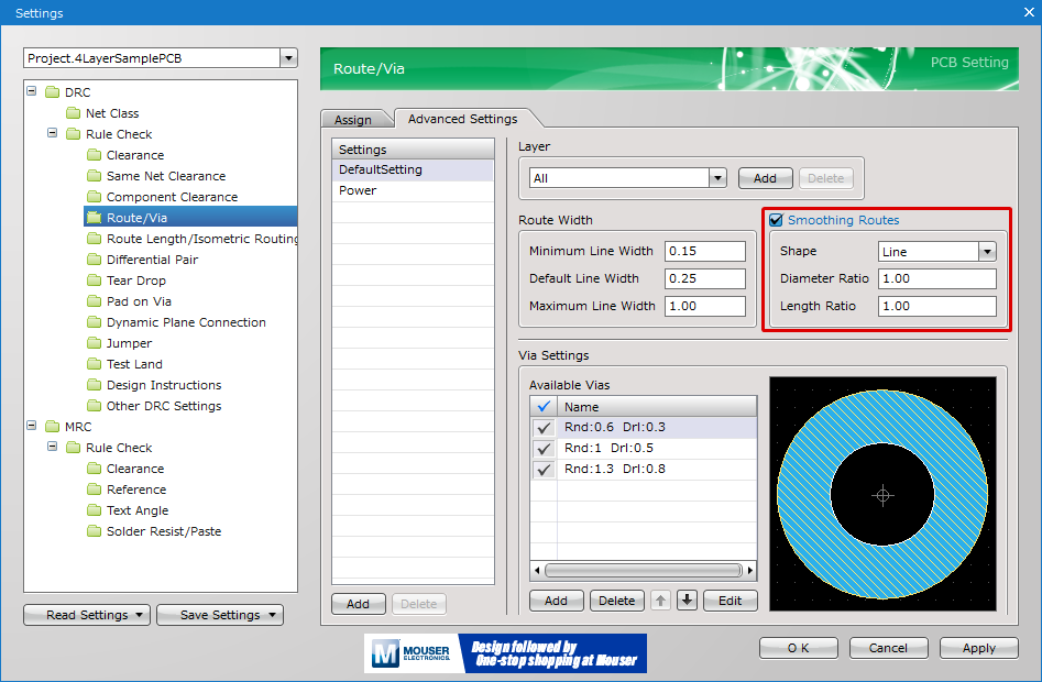
- Via and Smoothing Routes Settings can be configured from "Route" in PCB Settings.
- Tear Drop Settings can be configured from "Tear Drop" in PCB Settings.
Various Operations for Routing
The following will explain each operation for drawing routes.
Selecting the Route Menu
Toggling the Routing Cap Shape (Angle Route)
Changing the Bending Angle
Toggling the Corner Shape (Arc Route)
Switching the Angle
Toggling the Routing Start Direction
Editing the Route Width
Fix Creating Routes
Toggling Vias
Fix Creating Routes with Via
Routing at Pad Angle
Toggling Interpolating Route Mode
Toggling Allowance of Looping Routes
Pushback Route
Canceling a Route
Exiting Routing Mode
Selecting the Route Menu
Select [Create PCB] => [Route]
There are several other ways to perform this. Refer to About Executing Menus.
Toggling the Routing Cap Shape (Angle Route)
It is possible to change the Route Cap Shape to "Circle" or "Square".
By changing the Cap Shape to "Square", it is possible to create an Angle Route that is often used for high frequency design.
Route endcaps become square, and in addition to "Right Angle", it is also possible to change the "Bending Angle" to an arbitrary angle as shown below.
| Cap Shape "Circle" |
Cap Shape "Square" |
 |
 |
The following is the operation for toggling the route Cap Shape.
Method 1: When performing routing work, right-click and select [Toggle Routing Cap Shape]
* It can also be confirmed and changed from the Property Window.
Changing the Bending Angle
This is a function for changing the Corner of routes between 45 degrees, 90 degrees, and Free.
The following is an example of changing the bending angle for route corners.
Route Corner Bending Angle
| 45 degrees |
90 degrees |
Free |
 |
 |
 |
The following is the operation for changing the route corner bending angle.
Method 1: Right click, Select => [Change the Bending Angle]
Method 2: Press "S" on the keyboard
* It can also be confirmed and changed from the Property Window.
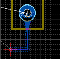
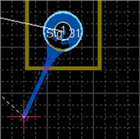
Switching the Angle
| Before Switching |
After Switching |
|
|
|
The following is the operation for switching the angle.
Method 1: Right click, Select => [Switch Angle]
Method 2: Press "X" on the keyboard
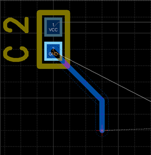
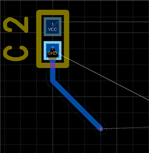
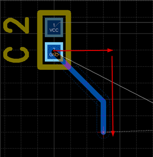
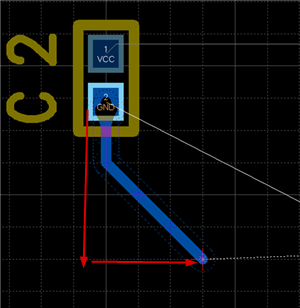
It is also possible to determine the pulling direction by tracking using the mouse pulling direction.
| When pulling to the right side first |
When pulling to the bottom first |
|
|
|
Toggle Routing Start Direction
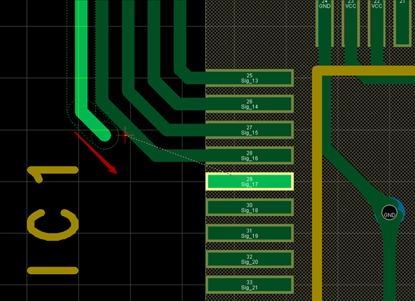
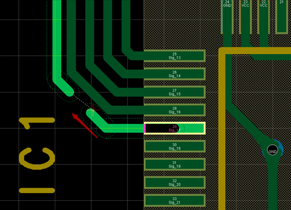
This is a function for changing the routing start direction.
This can be used when you want to perform routing from the opposite side while routing.
| Before Switching |
After Switching |
|
|
|
The following is the operation for toggling the routing start direction.
Method 1: While routing, Right click, Select => [Toggle Routing Start Direction]
Method 2: Press "Z" on the keyboard
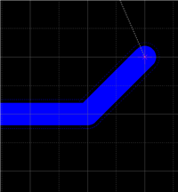
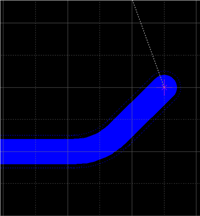
Toggling the Corner Shape (Arc Route)
Method: While routing, [Right Click] Select => [Toggle Corner Shape] => [Toggle Corner Shape]
| Line |
Arc |
|
|
|
For more details, refer to Toggle Corner Shape.
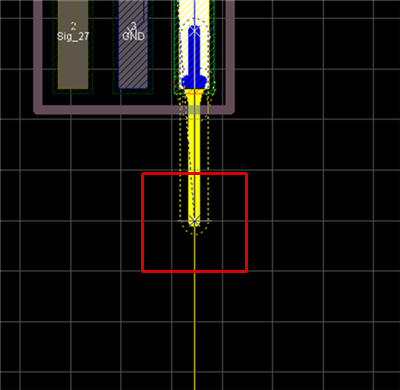
| Change the route width while routing. |
| (1) |
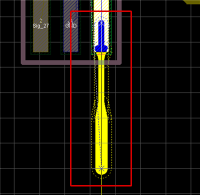
Click on the location where you want to change the Route Width. |
|
 |
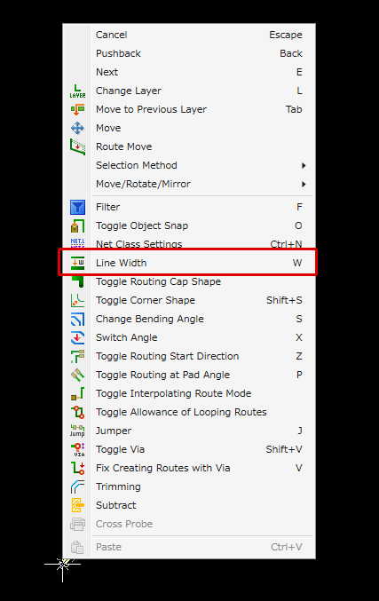
| (2) |
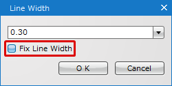
Right-click and select [Change the Line Width].
*Or, press the shortcut "W" key. |
|
 |
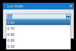
| *It is also possible to show the history of line widths by clicking a pull-down button and select from the list. Up to 5 line widths are saved in the history. |
|
 |
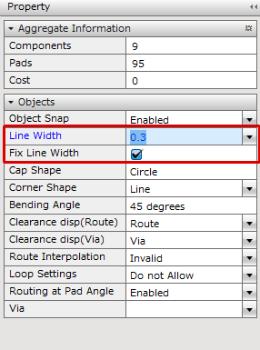
| *A line width can also be changed in the "Property Window". |
|
 |
| |
The Line Width will be changed in the middle. |
|
 |
| |
It can be confirmed from the Settings screen. |
|
 |
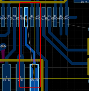
| The following will explain how to determine routes while routing. |
| (1) |
Click on the location where you want to determine the route. |
|
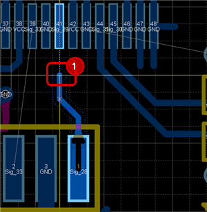 |
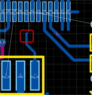
| (2) |
Right Click
Select => [Fix Creating Routes]. |
|
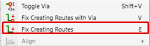 |
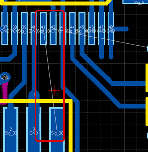
| |
The route will be determined.
* This can also be done by double-clicking while routing. |
|
 |
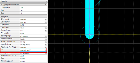
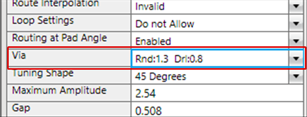
| When multiple Vias are registered to a route, you can confirm which Via is being used while routing. |
| |
While routing, the Via that is used will be displayed in the Property Window. |
|
 |
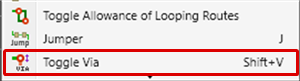
| (1) |
Right Click
Select => [Toggle Via]. |
|
 |
| |
The Via that is used will be toggled. |
|
 |
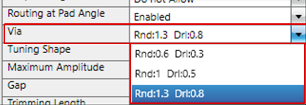
| |
Registered Vias can be confirmed from the Pulldown in Property. |
|
 |
| The following will explain how to determine routes by placing Vias while routing. |
| (1) |
Click on the location where you want to determine the route. |
|
 |
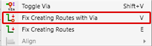
| (2) |
Right Click
Select => [Fix Creating Routes with Via]. |
|
 |
| |
The Via is routed and the route is determined. |
|
 |
Toggle Routing at Pad Angle
This is the function for adjusting the pull direction so that routes can be pulled from the pad in a straight line such as when a component is placed at an arbitrary angle.
| Routing at Pad Angle Enabled |
Routing at Pad Angle Invalid |
|
|
|
The following is the operation for toggling. The status will be shown in the Property Window.
Method 1: Right click, Select => [Toggle Routing at Pad Angle]
Method 2: Press "P" on the keyboard
Toggling Interpolating Route Mode
When the cursor position while routing is the same as the "X Coordinate"/"Y Coordinate" of a Pad/Via/Route on the same Net, routing is connected automatically by double clicking.
| Toggle Interpolating Route Mode Enabled |
Toggle Interpolating Route Mode Invalid |
|
|
|
The following is the operation for executing Toggle Interpolating Route Mode.
Method 1: While routing, Right-click, Select => [Toggle Interpolating Route Mode]
Method 2: From [Route Interpolation] in the Property Window, toggle Enabled/Invalid
Toggling Allowance of Looping Routes
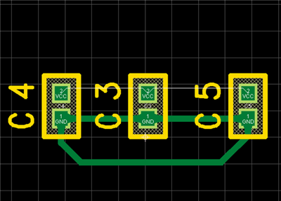
During routing work, it is possible to allow Looping Routes.
| Looping Routes Allowed |
Looping Routes Not Allowed |
|
|
|
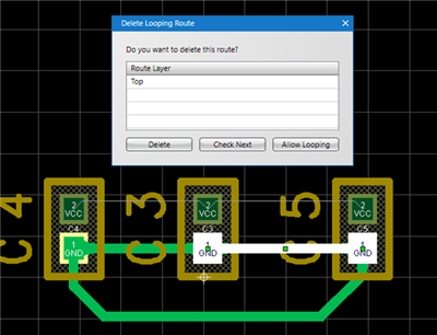
The following is the operation for executing Toggle Allowance of Looping Routes.
Method 1: While routing, Right click, Select => [Toggle Allowance of Looping Routes]
Method 2: Toggle from [Rout Loop Settings] in the Property Window
Pushback Route
When creating a route, you can return the corner to the previous status.
| Before Pushback |
After Pushback |
|
|
|
The following is the operation for executing pushback.
Method 1: Right click, Select => [Pushback]
Method 2: Press "Back" on the keyboard
Canceling a Route
When creating a route, it is possible to return to the status before drawing by canceling the route being created.
| Before Canceling |
After Canceling |
|
|
|
The following is the operation for executing pushback.
Method 1: Right click, Select => [Cancel]
Method 2: Press "Escape" on the keyboard
Exiting Routing Mode
The following is the operation for exiting Routing Mode.
When not creating a route,
Method 1: Right click, Select => [Cancel]
Method 2: Press "Escape" on the keyboard