

Schematic Capture : Schematic Settings
ERC Settings
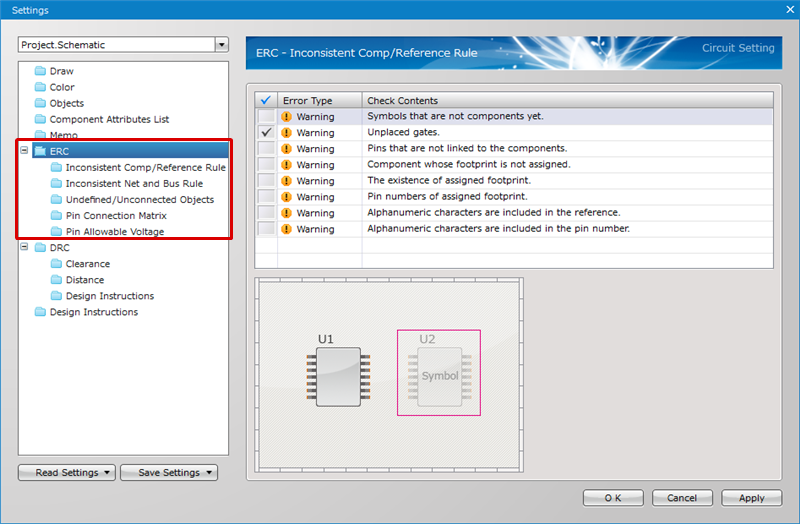
Configure ERC (Electrical Rule Check) settings.
The configured contents will be reflected to the ERC Results displayed after running the ERC.
For more details about opening the Schematic Settings screen, refer to About Schematic Settings.
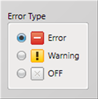
Error Type
The following are the types of errors that can be configured.
| Item | Content |
|
Error |
When there is a problem when running ERC, the result becomes an Error. |
|
Warning |
When there is a problem when running ERC, the result becomes a Warning. |
|
OFF |
Even when there is a problem when running ERC, the result is not shown. |
ERC Settings List
The following will explain the Check Contents of ERC Settings and their details.
Inconsistent Comp/Reference Rule
Inconsistent Net and Bus Rule
Undefined/Unconnected Objects
Pin Connection Matrix
Pin Allowable Voltage
Inconsistent Comp/Reference Rule
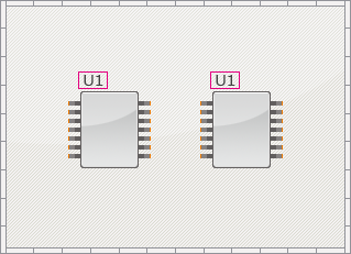
| Duplicated references. |
|
Error Check Type: Reference Duplication When there is a duplicate of a component Reference on the schematic, an error is detected. |
 |
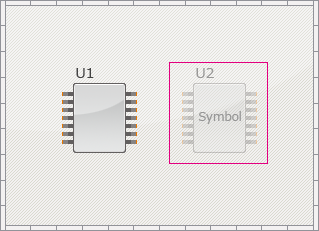
| Symbols that are not components yet. |
|
Error Check Type: Symbol which is not converted to Component When there is a symbol which is not converted to Component on the schematic, an error is detected. |
|
|
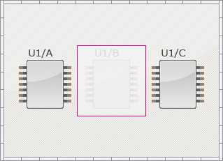
| Unplaced gates. |
|
Error Check Type: Unplaced Gate When all gates have not been placed for gate components on a schematic and there are unplaced gates, an error is detected. |
|
|
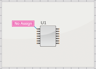
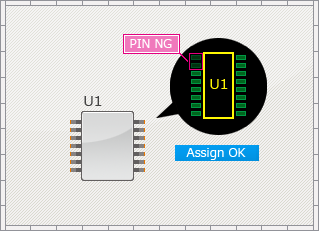
| Pins that are not linked to the components. |
|
Error Check Type: Pin Assignment Error (Assigned Number), Pin Assignment Error (Assigned Gate) When a PCB pad is not linked (assigned) to a component pin on the schematic, an error is detected. |
|
|
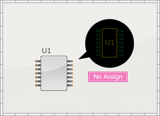
| Component whose footprint is not assigned. |
|
Error Check Type: Assignment of Footprint When a footprint is not assigned to a component on the schematic, an error is detected. |
|
|
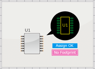
| The existence of assigned footprint. |
|
Error Check Type: Failed to Read Footprint When a footprint assigned to a component on the schematic does not exist in the master, an error is detected. |
|
|
| Pin numbers of assigned footprint. |
|
Error Check Type: Mismatch Pin Numbers of Footprint When the component on the schematic and the pin count of the footprint are different, an error is detected. |
|
|
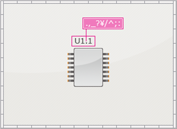
| Alphanumeric characters are included in the reference. |
|
Error Check Type: Reference character Violation When there is a non-half-size character in the Reference of a component on the schematic, an error is detected. |
|
|
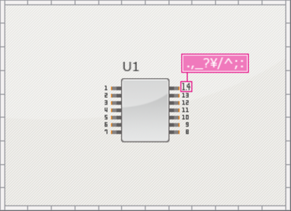
| Alphanumeric characters are included in the pin number. |
|
Error Check Type: Pin Number character Violation When there is a non-half-size character in the Pin No. of a component on the schematic, an error is detected. |
|
|
Inconsistent Net and Bus Rule
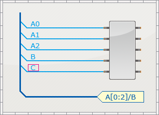
| Net connection that violates bus rule. |
|
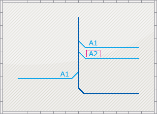
Error Check Type: Bus Rule Violation When there is a Net Connection that violates the Bus Rules set for buses, an error is detected. |
|
|
| Two-byte characters in net name. |
|
Error Check Type: Two-byte characters in Net Name When the Net Name contains a full-size character, an error is detected. |
|
|
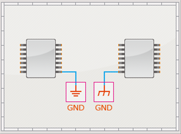
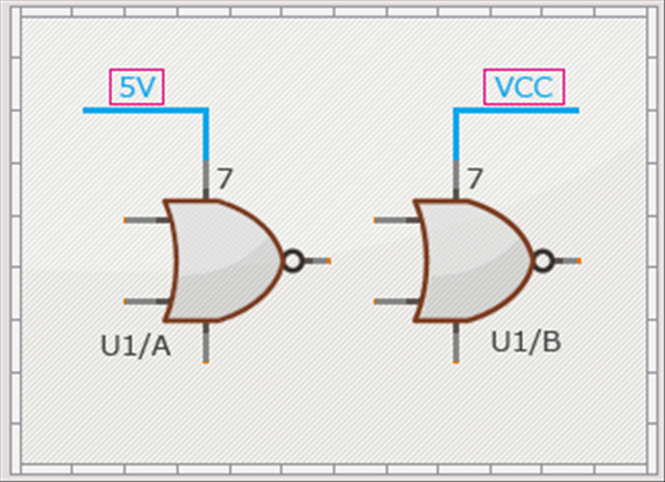
| Same net power supplies but different symbol. |
|
Error Check Type: Same Net Power Supplies Using Different Symbols Where there are different Power Supply Symbols placed with the same Net Name, an error is detected. |
|
|
| Same pins connected to different nets. |
|
Error Check Type: Same Pins Connected to Different Nets When the same pin is connected to different nets, an error is detected. |
|
|
| Single pin net. |
|
Error Check Type: Single Pin Net When there is no connection destination for a wire with the specified Net Name and it is a Single Pin Net, an error is detected. |
|
|
Undefined/Unconnected Objects
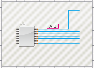
| Single wire connection to bus. |
|
Error Check Type: Single Wire Connection to Bus When there is a single connection among the wirings connected to a bus, an error is detected. |
|
|
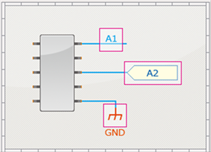
| Alone port. |
|
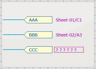
Error Check Type: Single Port Placement When only one port is placed and there is no destination address, an error is detected. |
|
|
| Undefined pin numbers. |
|
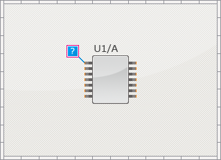
Error Check Type: Undefined Pin Number When a component Pin No. has not been input, an error is detected. |
|
|
| The connected mechanical components. |
|
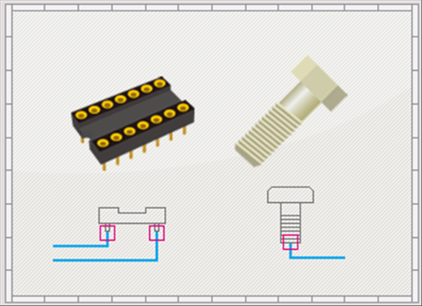
Error Check Type: Connection to Mechanical Component If a wire is connected when a component is specified to "Set as Mechanical Component (excluded from netlist)", an error is detected. |
|
|
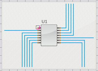
| Unconnected pins. |
|
Error Check Type: Unconnected Pin When there is an unconnected pin, an error is detected. |
|
|
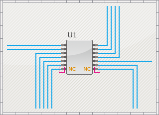
| Connection to the unconnected pins. |
|
Error Check Type: Connection to Unconnected Pin If a wire is connected even though the pin is specified as "Non Connection", an error is detected. |
|
|
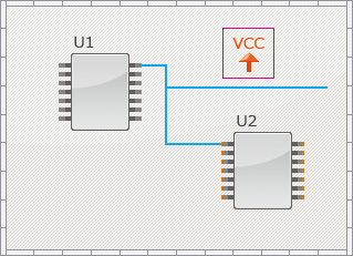
| Unconnected power supplies. |
|
Error Check Type: Unconnected Power Supply When there is an unconnected power supply, an error is detected. |
|
|
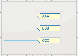
| Unconnected ports. |
|
Error Check Type: Unconnected Port When there is an unconnected port, an error is detected. |
|
|
| Unconnected wire end points. |
|
Error Check Type: Unconnected Wire When there is an unconnected wire end point, an error is detected. |
|
|
Pin Connection Matrix
| Pin Connection Matrix |
|
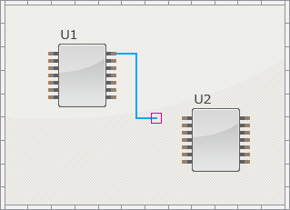
Error Check Type: Electrical Property Connection Violation By configuring the Pin Connection Matrix settings, when running ERC, the Electrical Attributes for pins connected to pins are checked. |
|
|
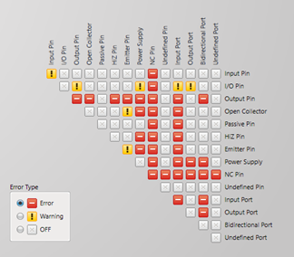
There are the following methods for configuring Pin Connection Matrix settings.
| Item | Content | Setting Methods |
|
Individual Settings |
Configure electrical attributes individually. |
Click the button where the column/line header electrical attribute names intersect |
|
Batch Settings |
Configure all electrical attribute settings for a column/line. |
Click a column/line header electrical attribute name |
Configure the pin electrical attribute settings from the Pin Attribute Settings screen of the Edit Component dialog.
For more details, refer to STEP 7: Pin Settings in Creating Components.
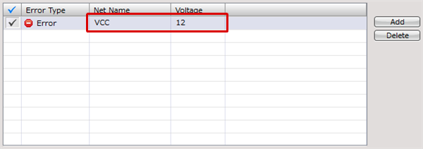
Pin Allowable Voltage
| Pin Allowable Voltage |
|
Error Check Type: Pin Allowable Voltage Violation (Out of Range), Pin Allowable Voltage Violation (Format) Pin Allowable Voltage verifies that the voltage of power supply connected to a component pin is within the allowable voltage range for the pin. |
|
|
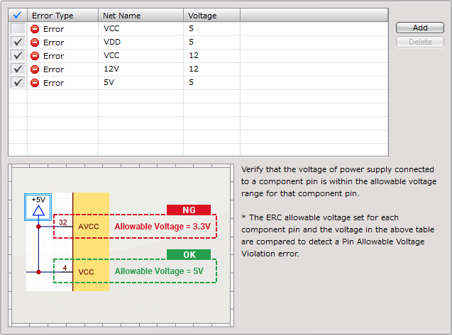
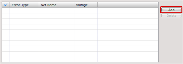
| Pin Allowable Voltage Settings |
| The instructions that follow explains how to configure the Pin Allowable Voltage settings. Setting a voltage to a power supply net allows you to verify that the voltage of the net connected to a component pin is within the allowable voltage range for the pin. |
|
 |
|
 |
To perform this verification, you also need to specify allowable voltages for component pins. For details, see the STEP 7: Confirming Pin Settings page.