

Quadcept : Creating Components
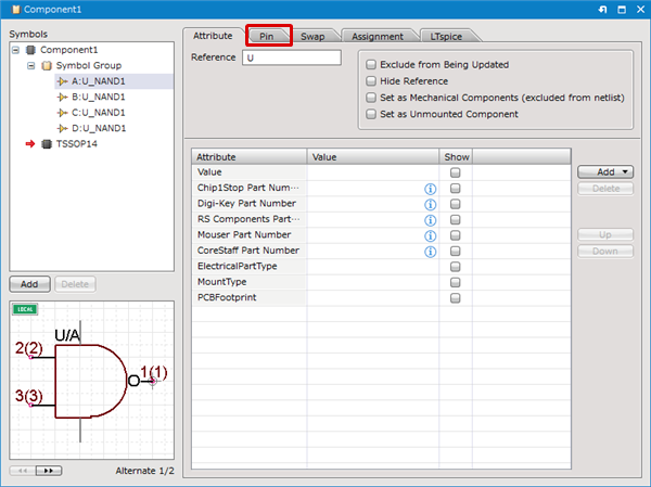
STEP 7: Confirming Pin Settings
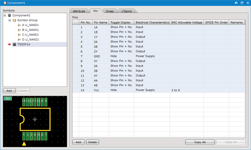
The next step is to configure pin settings. For pins, you can configure setting for "Pin No.", "Pin Name", "Toggle Display", "Electrical Characteristics", "ERC Allowable Voltage", "SPICE Pin Order" and "Remarks".
Ex.) Pin Settings
| Item | Description |
|
Pin No. |
Sets the Pin No. This is the reference for the Netlist and PCB linking. |
|
Pin Name |
Indicates the Pin Name. It is possible to display this on the schematic to make the pin characteristics easy to understand. |
|
Toggle Display |
You can select from "Hide", "Show All", "Show Pin", "Show Pin + Name", and "Show Pin + No.", and toggle the pin display status. |
|
Electrical Characteristics |
You can select from "Input Pin", "I/O Pin", "Output Pin", "Open Collector Pin", "Passive Pin", "HiZ Pin", "Emitter Pin", "Power Supply", "NC Pin", "Undefined Pin", and "Unused Pin", and set the Electrical Characteristics of the pin. When the electrical characteristics of a pin is set as "NC", the checkbox of "Non Connection" for the pin will be automatically checked when the component is placed on a schematic sheet. The pin point of the "Non Connection" pin will change into a "X"-shaped mark and the pin will not be checked by an ERC item, "Unconnected Pins". Also, if a wire is connected to the "Non Connection" pin, you can find it by a check item, "Connection to the unconnected pins" of ERC. If you set "Unused Pin" when there is a difference in the Pin Count between the symbol and footprint such as "Mounting hole (Boss hole)" or "Heat Pad", you can avoid "Assignment" violations. |
|
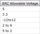
ERC Allowable Voltage |
Use this field to specify the allowable voltage for the pin.
The allowable voltage for each pin will be checked by ERC when the pin is connected to the net specified in the ERC-Pin Allowable Voltage settings. If the connected voltage is out of range, an ERC error will occur. The pins without any values in their ERC Allowable Voltage field will not be checked by ERC. (They will also not be checked if only spaces are entered.) |
|
SPICE Pin Order |
In order to run a simulation in LTspice, you need to map the symbol pins to the SPICE model nodes. For details, see the SPICE Pin Order page. |
|
Remarks |
You can enter comments for pins. |
Options/Controls
| Item | Description |
|
Add |
Adds a pin on the pin list. |
|
Delete |
Deletes selected pin(s) on the pin list. |
|
Copy All |
Copies the contents of the Pin List to the clipboard. The contents can be confirmed and edited by pasting to a text editor or Excel, etc. |
|
Paste All |
Pin List Information that was edited using a text editor or Excel, etc., can be pasted. |
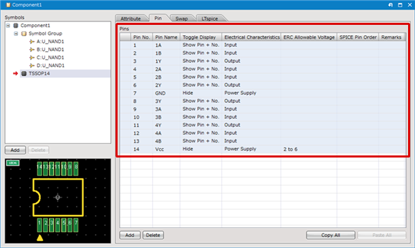
| Changing Pin Settings |
| The following will explain how to change pin settings. |
|
 |
|
 |