The following will explain how to create a component using the following sample.
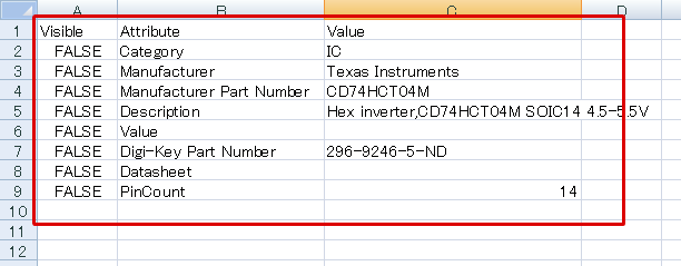
Maker Part No.: CD74HCT04M
| The following will explain how to create an IC (CD74HCT04M)as a sample. |
| ■ Preparation 1 |
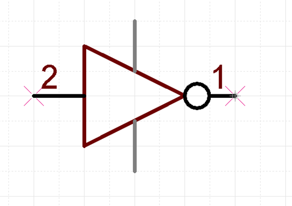
| Prepare a Gate Symbol |
Use "U_NOT1".
* Configure Alternate Settings for "U_NOT_Alt". |
| For more details on the creation method, refer to Creating Symbols. |
|
 |
| ■ Preparation 2 |
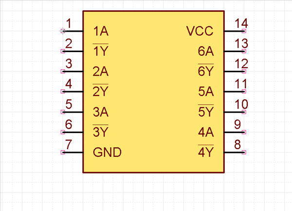
| Prepare a symbol. |
| Use "CD74HCT04M". |
| For more details on the creation method, refer to Creating Symbols. |
|
 |
| ■ Preparation 3 |
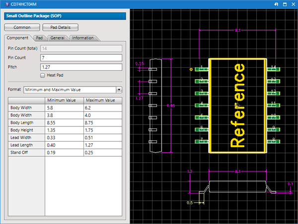
| Prepare the "IPC Footprint |
| Use "CD74HCT04M". |
| For more details on how to create footprints, refer to Creating IPC Footprints. |
|
 |
| (1) |
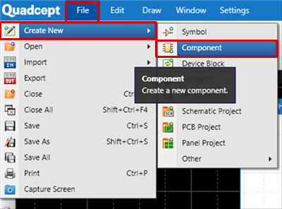
[File]
=> [Create New]
=> [Component]
=> The component creation screen will open. |
|
 |
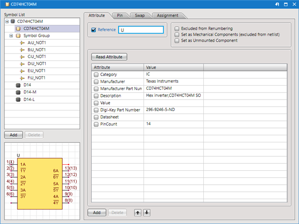
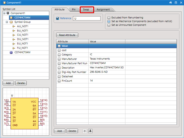
| (2) |
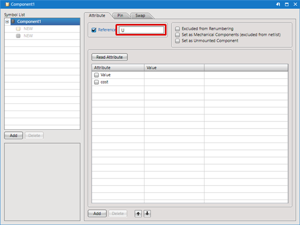
Set up the reference text in Reference
"U" is set because it is an IC. |
|
 |
| (3) |
Copy the Attribute from Excel using Ctrl+C. |
|
 |
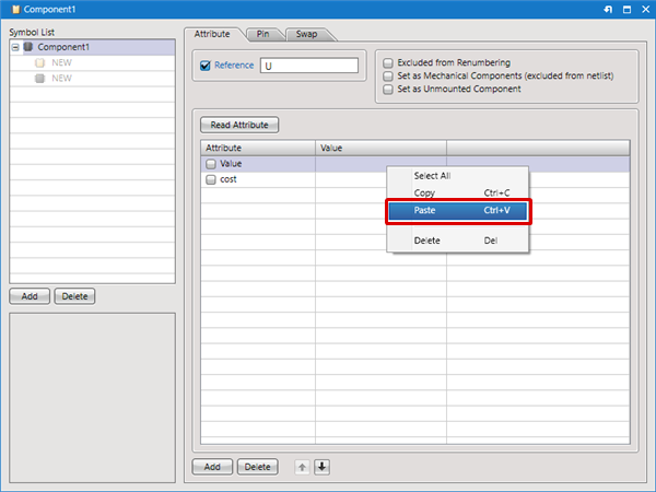
| (4) |
Right-click on the Attribute List
=> Click [Paste] |
|
 |
| |
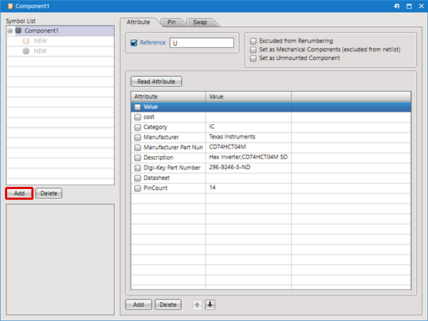
The Attribute will be pasted.
Next, register a symbol. |
| (5) |
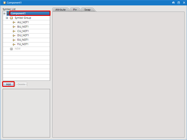
From the Symbol List, click the "Add" button |
|
 |
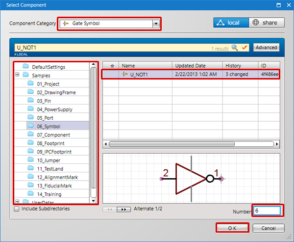
| (6) |
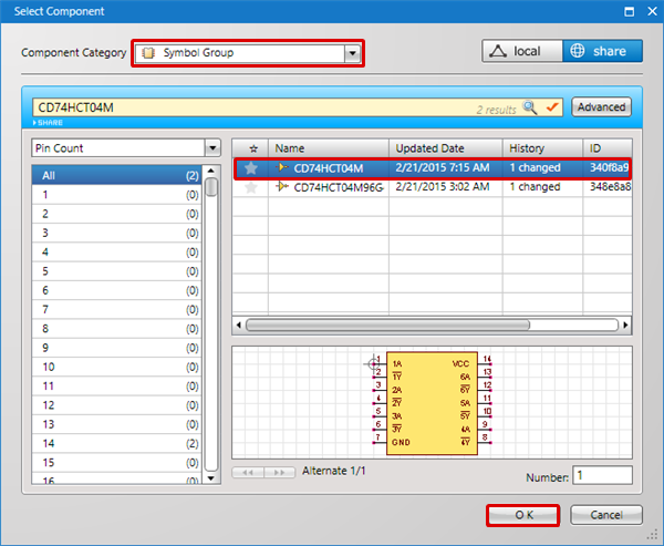
Set "Symbol Group" as the Component Category |
| (7) |
Select a directory |
| (8) |
Select the symbol "U_NOT1 |
| (9) |
Input "6" in Number: |
| (10) |
Click "OK" |
|
 |
| (11) |
Six symbols will be registered. |
|
 |
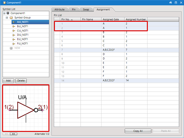
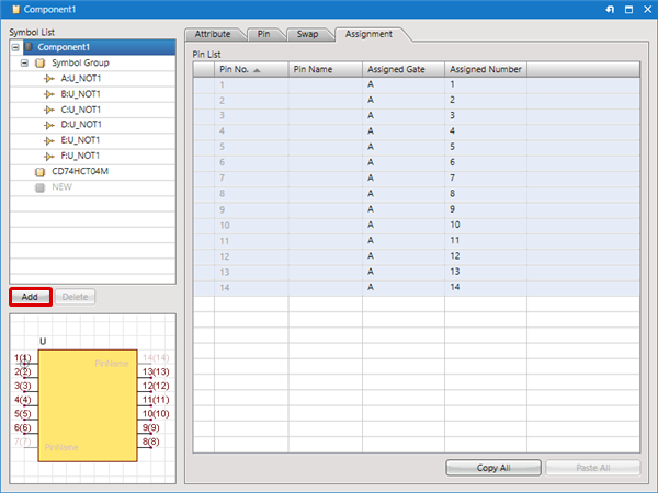
| (12) |
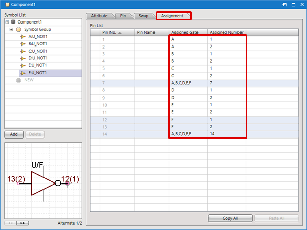
Set the Pin Assignment. |
| |
Click the "Assignment" tab.
The number in parentheses in the Preview indicates the Symbol Pin No.
Reference the Symbol Pin No. and set the "Assigned Gate" and "Assigned Number".
* "Assigned Gate" indicates the gate that is assigned, and "Assigned Number" indicates the Symbol Pin No. that is assigned. |
| |
For more details, refer to Confirming Pin Assignment. |
|
 |
| (13) |
From the Symbol List, select "Component1" |
| (14) |
Click the "Add" button |
|
 |
| (15) |
Set "Symbol Group" as the Component Category |
| (16) |
Select the symbol "U_IC_14PIN |
| (17) |
Click "OK" |
|
 |
| (18) |
Click the "Add" button |
|
 |
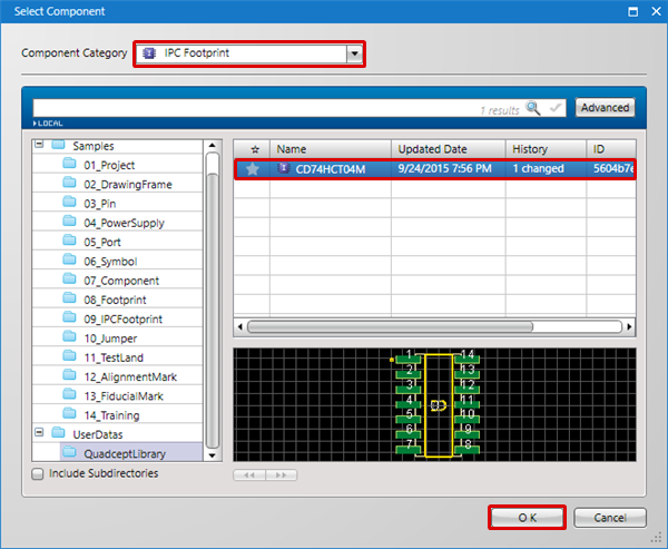
| (19) |
Set "IPC Footprint" as the Component Category |
| (20) |
Select IPC FootprintCD74HCT04M |
| (21) |
Click "OK" |
|
 |
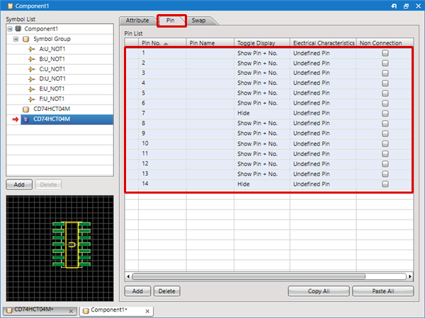
| |
Confirm pin settings. |
| (22) |
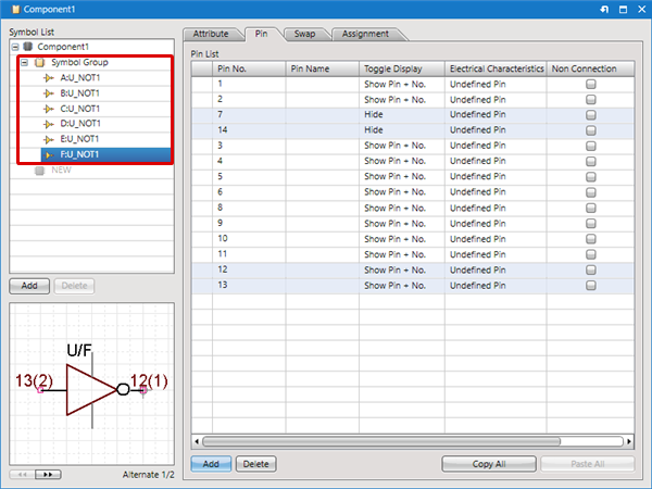
Click the "Pin" tab. |
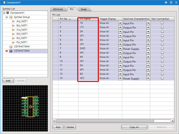
| (23) |
Configure settings for "Pin Name" and "Electrical Characteristics |
|
 |
| |
Pin settings are complete. |
|
 |
| |
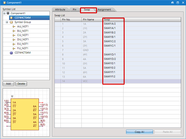
Next, confirm Swap Information. |
| (24) |
Click the "Swap" tab. |
| (25) |
Confirm Swap Information
* For more details about swap, refer to Registering Swap Information. |
|
 |
| |
Swap settings are complete. |
|
 |
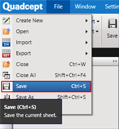
| (26) |
[File]
Click => [Save]
==> "Save (Component)" will be displayed. |
|
 |
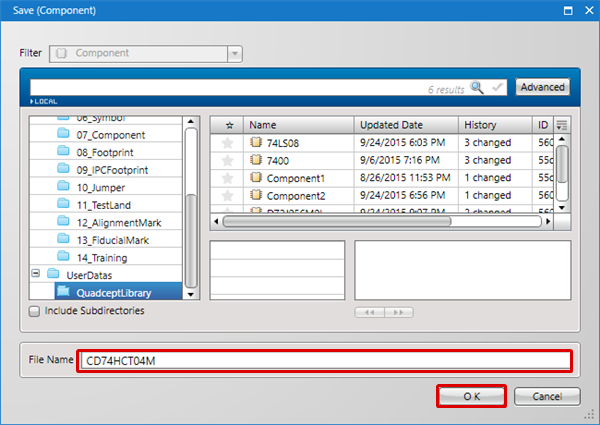
| (27) |
Select "Directory", input the File Name, and then click "OK" |
|
 |
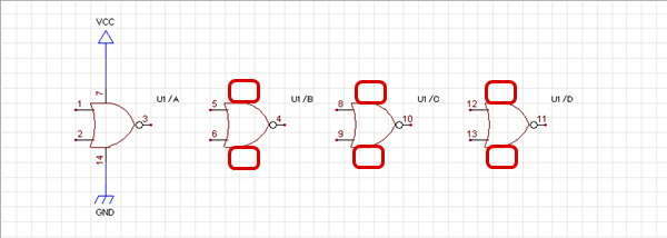
When a component is created using a Gate Symbol, if a wire is connected to overlapping pins,
unconnected Gate Symbol pins will automatically be hidden. For power supply characteristics pins, etc., it is convenient to overlap and create.
[Before Connecting Wires]
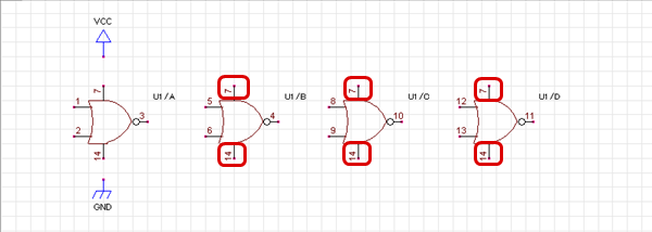
[After Connecting Wires]