

PCB Layout CAD : Net Operation
Connection Point
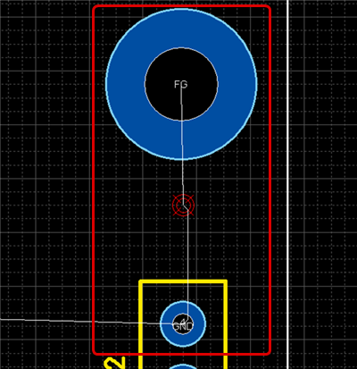
Connection Point is a function for setting one point as a reference potential. It is also referred to as a "Single Point Ground" or "Single Point Earth".
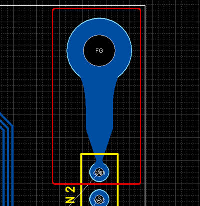
By combining two different GNDs into a single [Earth Point], it is possible to minimize the potential difference, which is a countermeasure for noise.
Using this function, schematic and PCB affinity is improved, and the single earth portion is considered by the DRC of the PCB design side, so a visual check is no longer needed, which results in greatly reducing routing work.
Connection Point Usage Example

| Drawing a Connection Point |
| The following is the operation for a Connection Point. |
|
 |
|
 |
|
 |
|
 |
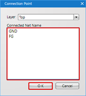
After placement, connection can be done using Add Net.
Each Operation for Drawing a Connection Point
The following will explain each operation for drawing a connection point.
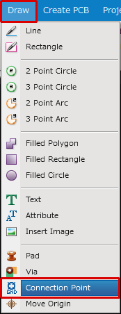
Selecting the Connection Point Menu
Exiting Connection Point Mode
Selecting the Connection Point Menu
Select [Draw] => [Connection Point]
There are several other ways to perform this. Refer to About Executing Menus.
Exiting Connection Point Mode
The following is the operation for exiting Connection Point mode.
When not creating a Connection Point,
Right click, Select => [Cancel].
* Press "Escape" on the keyboard.