

PCB Layout CAD : DRC/MRC Settings
About DRC/MRC Settings
In the PCB Settings, you can configure the DRC Settings and MRC Settings for the currently active PCB design file.
By running DRC/MRC, verification results based on the set contents can be displayed in an Error List, which allows you to easily confirm and correct errors.
| Content | |
|
DRC |
This stands for Design Rule Check, and verifies whether designed items violate Design Rules such as Route Rules. |
|
MRC |
This stands for Manufacturing Rule Check, and verifies whether rules related to manufacturing such as Clearance between components and Reference placement angles are violated. |
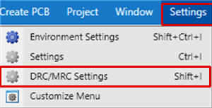
| Opening DRC/MRC Settings |
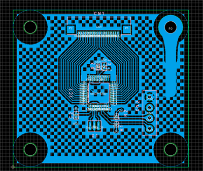
| The following will explain how to configure DRC/MRC Settings. To configure DRC/MRC Settings, you first need to open the relevant PCB in the Project. |
|
 |
|
 |
|
|
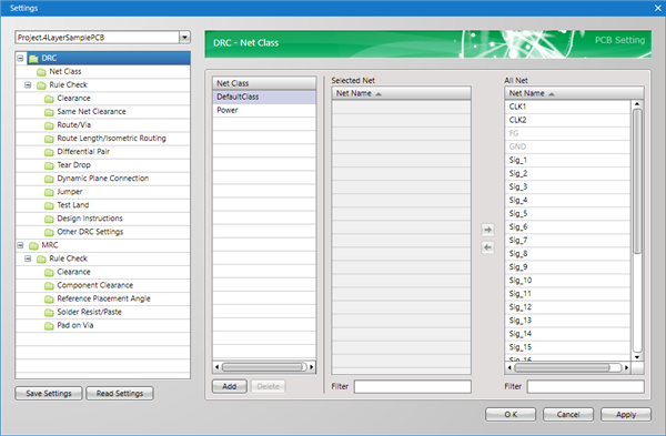
In the Settings dialog, each setting is displayed on the left in tree format.
Select the item you want to configure, and change the setting.