PCB Layout CAD : Exporting (CAMs, Drills, Component Coordinates, etc.)
Printing PCBs
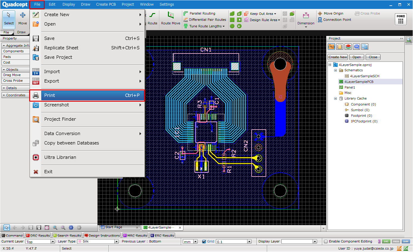
This page explains how to print your PCB designs.
With the Batch Output command, you can export multiple types of documents such as Gerber files and NC drill files at once.
| Item | Description |
|
Prints using the display status currently displayed in the design work area. |
|
|
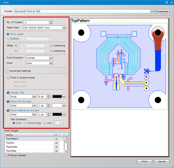
Prints using the specified display set in the PCB Print settings. |
|
|
Batch Output is a function for handling processing of all finishing work for PCBs such as Gerbers, NC Drills, NC Drill Lists, Component Coordinate Export, and Export BOM. The settings can be saved, so once Batch Output settings have been configured, it can be executed with a single click when releasing a PCB. In addition, by selecting PDF Print in the Print Settings, you can also execute PDF export. |
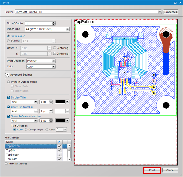
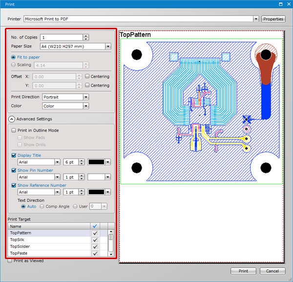
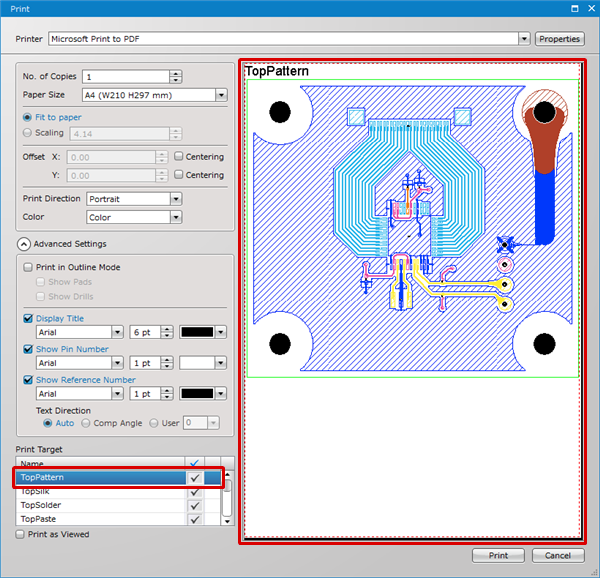
Print Screen Details
| Item | Description | ||||||
|
Printer |
Configures printer settings for export targets. |
||||||
|
Printer Advanced Settings |
Configures detailed settings for the selected printer. |
||||||
|
Number of Copies |
Specifies the Number of Copies. For project print, this is the total print number. |
||||||
|
Paper Size |
Sets the paper size for printing. |
||||||
|
Fit to paper |
Scaling is adjusted so that it automatically fits to the paper size. |
||||||
|
Scaling |
Printing is performed according to the specified scale. |
||||||
|
Offset |
It is possible to set the offset for the whole drawing position such as when you want to have a larger margin on the left side. |
||||||
|
Print Direction |
It is possible to select either "Portrait" or "Horizontal" for the Print Direction. |
||||||
|
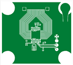
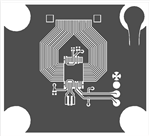
Color |
It is possible to select either "Color", "Grayscale", or "Black and white" as the Color setting.
|
||||||
|
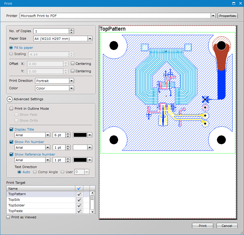
Advanced Settings |
Enables to open advanced print settings. |
||||||
|
Print in Outline Mode |
When "Print in Outline Mode" is checked, it is possible to print a PCB in outline. You can also toggle the visibility of pads and drills.
|
||||||
|
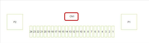
Display Title |
When this is checked, a "Name" in the "Print Target" is displayed at the top of the sheet as a title. |
||||||
|
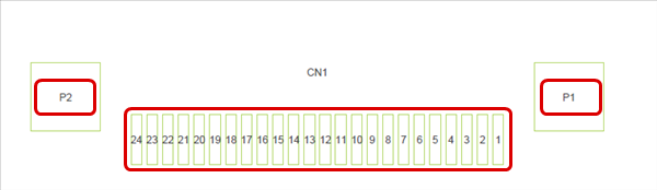
Show Pin Number |
When this is checked, the Pin No. text is displayed at the center of a pad. |
||||||
|
Show Reference Number |
When this is checked, the Component No. text is displayed at the center of a component. |
||||||
|
Text Direction |
Enables to specify the orientation of reference numbers by selecting one of the following options: "Auto", "Comp Angle" and "User". Auto : Ex.) User : 90 Degrees
|
||||||
|
Print Target |
It is possible to confirm the sheets that are the Print Target. |
||||||
|
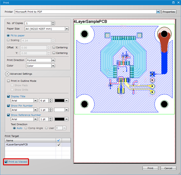
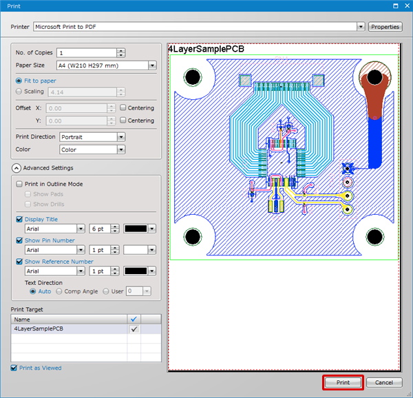
Print as Viewed |
Prints using the display status currently displayed in the design work area. |
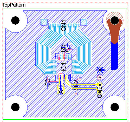
| Print as Viewed |
| The instructions that follow explain how to print a PCB design currently displayed in the design area. |
|
 |
|
 |
|
 |
|
 |
| Printing PCBs |
| The instructions that follow explain how to print your PCB design according to the combination of layers specified in the PCB Print settings. |
|
 |
|
 |
|
 |
|
|