

PCB Layout CAD : Exporting (CAMs, Drills, Component Coordinates, etc.)
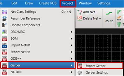
Exporting Gerbers
After designing is completed, export the Gerber data, which is one of the types of data sent for manufacturing.
Data Normally Needed for Board Creation:
- Gerber Data
- NC Drill Data
Depending on the need, the following may be needed.
- NC Drill List
- Component Coordinates, etc.
*******With Quadcept, it is also possible to group the above and export using Batch Output.
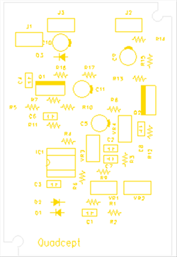
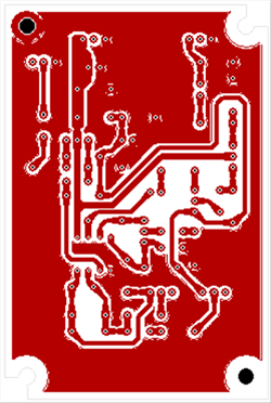
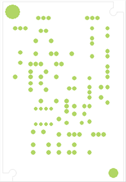
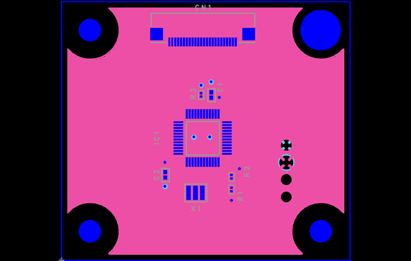
Gerber Data Example
| Silk Gerber | Pattern Gerber | Solder Resist Gerber |
|
|
|
|
The following will explain how to execute Export Gerber individually.
| Exporting Gerbers |
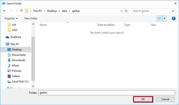
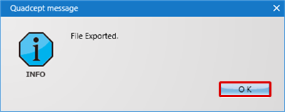
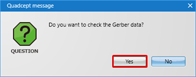
| The following will explain how to export Gerber data. |
|
 |
|
 |
|
 |
|
 |
|
 |
For more details about confirming Gerbers, refer to Opening Gerber Data.
For more details about Export Gerber Settings, refer to "Gerber" in PCB Settings.
Objects with a Line Width of "0" are output using Aperture 0 after the Warning Message is displayed.