

PCB Layout CAD : DRC/MRC Settings
Route/Via
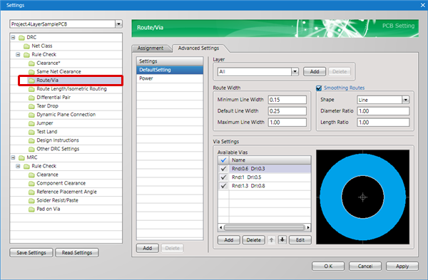
Configure Route Width Default values and configure the Minimum Line Width and Maximum Line Width that will be checked when executing Run DRC.
It is also possible to specify the Shape for Smoothing Routes when the Route Width is changed during designing, and to set the Via Shape used for toggling layers while routing.
With DRC, it is checked whether unregistered Vias are used, and Route Width Violations are checked.
For more details about opening the DRC/MRC Settings screen, refer to About DRC/MRC Settings.
Example Route Settings
Setting Method
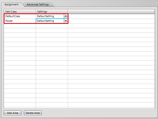
First, in Settings, there is an "Assignment" tab and "Advanced Settings" tab.
The "Advanced Settings" tab is used for configuring actual settings, and the "Assignment" tab is used for configuring which settings are assigned to which Net.
About the Work Procedure
STEP 1: Create a Net Class from the "Net Class" item
STEP 2: Configure settings in the "Advanced Settings" tab
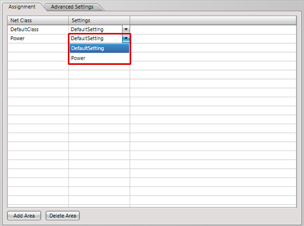
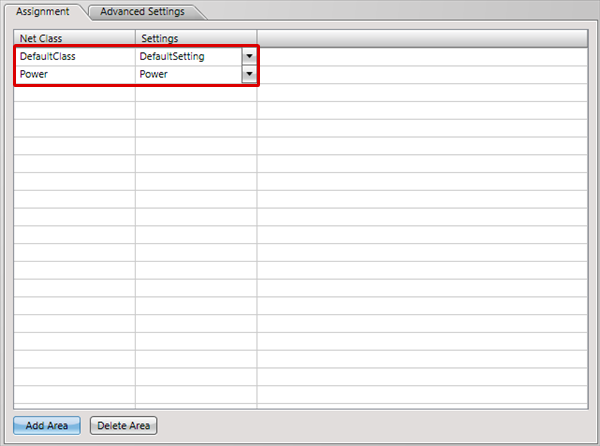
STEP 3: Assign settings to the Net Class in the "Assignment" tab
The following will explain each setting tab.
Explanation of Each Setting Tab
| Tab Name | Content |
|
It is possible to assign the "Settings" that are applied to Nets set in the "Net Class". For example, you can create a "Power Supply Net Class (GND, VCC)" Net Class, and assign the setting for "Power Supply Net Settings". |
|
|
Configures actual settings. |
Advanced Settings
For more details about adding settings, refer to Adding Settings.
Route Settings
Example Route Settings
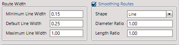
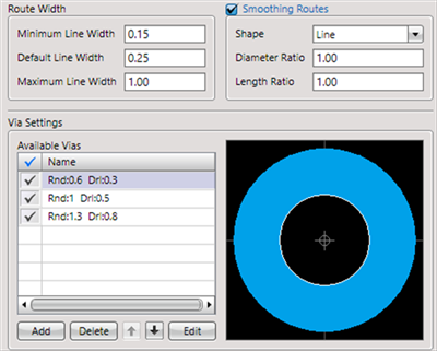
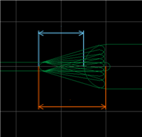
Route Width
| Item | Content |
|
Minimum Line Width |
This item is checked by "Online DRC" and "Run DRC". When a route width is smaller than a specified value, a "Route Width Violation" error will be detected. |
|
Default Line Width |
Sets the Route Width that applies when starting to draw a route. |
|
Maximum Line Width |
This item is checked by "Online DRC" and "Run DRC". When a route width is larger than a specified value, a "Route Width Violation" error will be detected. |
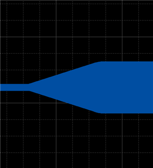
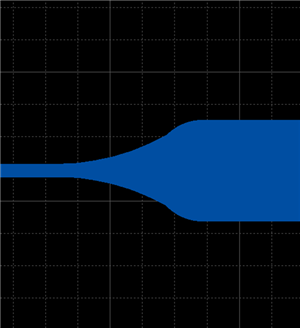
Smoothing Routes
| Item | Content | ||||
|
Smoothing Routes |
This is a check for whether to execute Smoothing Routes. When Smoothing Routes is enabled, this applies to all routes including routes that have already been drawn and routes that will be drawn. |
||||
|
Shape |
Specifies the shape for Smoothing Routes.
* "Diameter Ratio": Specifies the smoothing diameter ratio for routes with a thick Route Width. (Set this to 1.0 or smaller.) |
Via Settings
It is also possible to set the Via Shape that applies automatically for toggling layers while routing.
Multiple registration is also possible, and you can confirm which Via applies from the "Via" item in the Property Window while routing.
To toggle among multiple registered Vias, toggle using the "Via" item in the Property Window, or change it using the Right Click Menu => [Toggle Via].
Example Via Settings
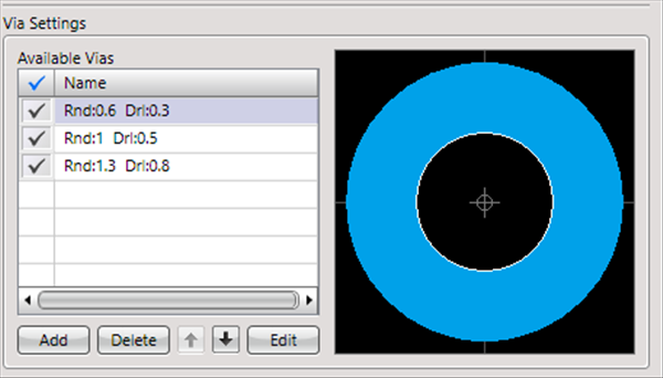
The Via at the top of Available Vias is the default Via.
To change the Via while working, select a Via from "Via" in the Property Window or on the Select Via screen that appears when toggling layers using the "L Key".
For more details, refer to Routing Operations.
The shapes of Vias that have already been drawn will not be changed.
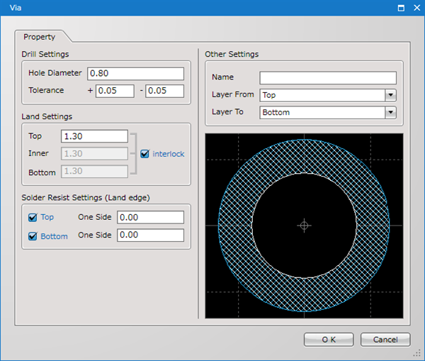
Drill Settings
| Item | Content |
|
Hole Diameter |
Sets the drill diameter. |
|
Tolerance |
Sets the tolerance for the drill diameter. This is shown for NC Drill Files and Print NC Drill Lists. |
Land Settings
| Item | Content |
|
Top |
Sets the land diameter of the Top surface. |
|
Inner |
Sets the land diameter of the Inner layer. |
|
Bottom |
Sets the land diameter of the Bottom surface. |
Solder Resist Settings(Land edge)
| Item | Content |
|
Top |
Solder Resist Settings for the Top surface. |
|
Bottom |
Solder Resist Settings for the Bottom surface. |
Other Settings
| Item | Content |
|
Pad Name |
You can give an arbitrary name for the created Via shape. This does not need to be set. Ex.) MIiniVia, etc. |
|
Layer From |
Sets Layer From for the Via. |
|
Layer To |
Sets Layer To for the Via. |
* Vias are through from Layer From to Layer To.
Specify the Layer From and Layer To for Inner Via Holes (Non Through holes between necessary layers without passing through in order to connect Conductors that exist in different layers in the Inner Layers of a board).
Layer Settings
For more details, refer to Layer Settings.
Assignment Settings
| "Assignment" Settings |
| It is possible to assign the "Settings" that are applied to Nets set in the "Net Class". |
|
 |
|
 |
|
 |