Schematic Capture : Adding Memos
About Memos
It is possible to place Memos including the knowhow of the circuit designer, design specifications, and work instructions as comments on schematics.
Design Instructions, technical knowhow (knowledge), in-house memos, and printed circuit board design instructions, which in the past needed to be created in a separate document, can now be shown or hidden on the screen using a Memo Layer.
Because it is compatible up to print approval, the intent of the circuit designer can properly be notified to the person in charge of the printed circuit board design.
It is now possible to input memo titles and content in Japanese, and it is possible to change the color of the title bar.
Using layers allows you to quickly confirm various information including Design Instructions, knowledge, and TODOs.
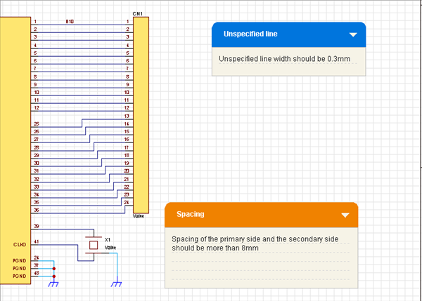
Using the Memo Layer
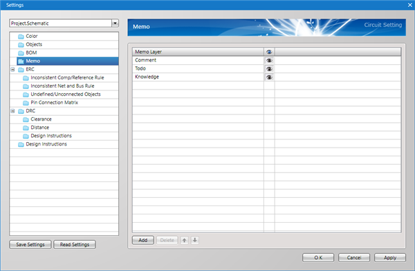
Regarding memos to be registered, the input layer can be divided.
The designer can effectively use memo contents by arbitrarily adding/editing memo layers. (Can be shown or hidden)
About Memo Layer Settings, see Memos.
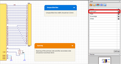
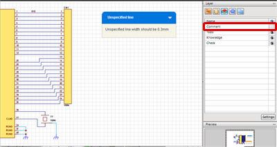
You can toggle Show Memo ON/OFF from the Layer Window.
| Show Comment Layer | Hide Comment Layer |
 |
 |
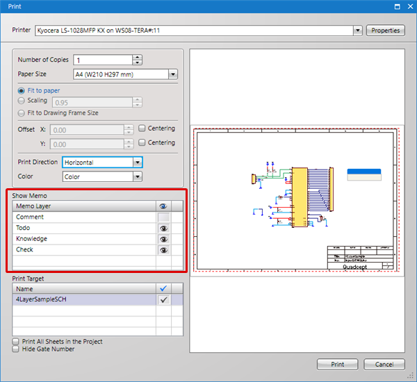
They can also be shown or hidden for printing.
Memo Types
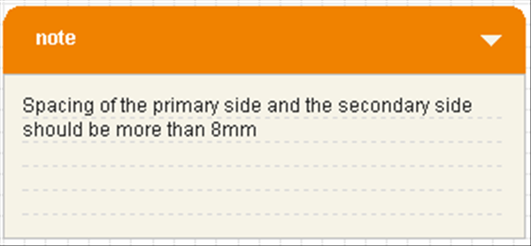
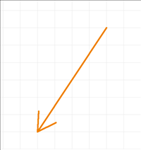
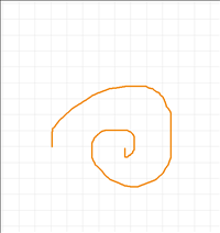
There are the following types of memos.
| Note | Arrow | Free Line |
|
|
|
|


