

PCB Layout CAD : PCB Settings
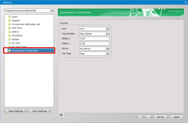
Component Coordinates
Export component position coordinates from the PCB for component mounting.
You can select the Component Coordinate Origin Point from "Component Origin Point"/"Pad Center".
For more details about opening the PCB Settings screen, refer to About PCB Settings.
Sample Component Coordinates
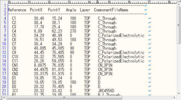
A prerequisite is that processing is done using each mounting device format according to the BOM, so components that are "Set as Unmounted Component" will also be exported.
Component Coordinates
| Item Name | Content |
|
Unit |
The unit can be selected from "mm, "mil", or "inch". |
|
Coordinates |
It is possible to select from "Component Origin Point"/"Pad Center". |
|
Offset X |
When the Board Origin Point and Reference Origin Point for the component coordinates are different, it can be adjusted. The X Coordinate is offset. |
|
Offset Y |
When the Board Origin Point and Reference Origin Point for the component coordinates are different, it can be adjusted. The Y Coordinate is offset. |
|
Mirror |
Use this control to generate a component coordinates file with the flipped coordinate information. Use the drop-down list to choose from the following: No Mirror : A component coordinates file is output with the viewed-from-top coordinate information. |
|
File Type |
Use this control to specify the file type. Use the drop-down list to choose Text or CSV. |
Exporting Component Coordinates
There are the following methods for executing Component Coordinate Export.
- Click the  icon of the PCB Settings Component Coordinate screen
- Open a PCB document, [Project] => [Component Coordinate Export] => [Component Coordinate Export]
- Batch Output