

Schematic Capture : Draw
Drawing Attributes
An attribute is a character string used when a process is performed on the software such as the Create Schematic screen and Drawing Frame.
It is applied to the character string (Reference, Component Attribute, Pin Name/Pin No., and Drawing Frame Sheet No.) for executing a particular operation.
With Quadcept, users can arbitrarily place Drawing Frame Macro Attributes and Drawing Frame Attributes.
The following will explain Attribute Types and each operation for drawing attributes.
Attribute Types
System Attribute Types
Selecting the Attribute Menu
Drawing an Attribute
Rotating an Attribute
About System Attributes
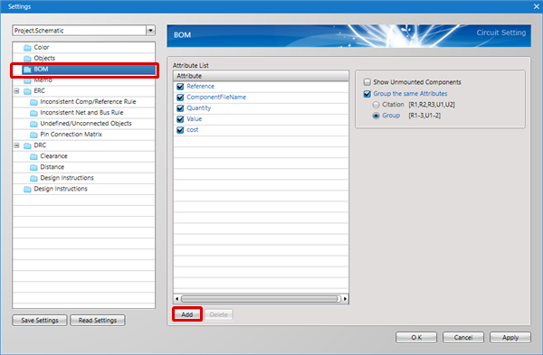
Adding/Editing Attributes
Deleting an Attribute
Exiting Attribute Mode
Attribute Types
An attribute is a character string that can execute a process on the software.
Things defined as System Attributes are those where a processes has already been set.
You can freely add frequently used attributes arbitrarily.
Ex.) Schematic Title, Designer, Approver, etc., for a Drawing Frame
Maker, Resistance Value, etc., for a Component Attribute
System Attribute Types
| Attribute | Content | Example |
|
ExportBom |
Shows the component's "Export BOM". |
True/False |
|
ExportNet |
Shows the component's "Export Netlist". |
True/False |
|
IsUnAnnotateReference |
Shows the component's "Lock when Renumbering References" |
True/False |
|
Quantity |
Shows the number of components when grouping components with the same attribute when exporting a BOM. |
10 |
|
Reference |
Shows the component's "Reference". |
U10 |
|
PinName |
Shows the pin's "Pin Name". |
CLK |
|
PinNo |
Shows the pin's "Pin Number". |
5 |
|
ComponentFileName |
Shows the Component Name. |
C3216X7R1C685K |
|
SymbolFileName |
Shows the Symbol Name. |
capacitor |
|
FootPrintFileName |
Shows the Footprint Name or IPC Footprint Name. |
3216 |
About Drawing Frame Attributes, refer to Macro Attributes.
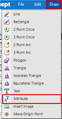
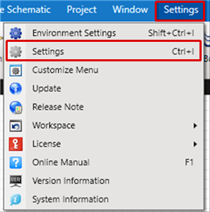
Selecting the Attribute Menu
Select [Draw] => [Attribute]
There are several other ways to perform this. Refer to About Executing Menus.
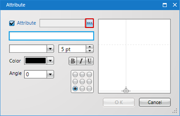
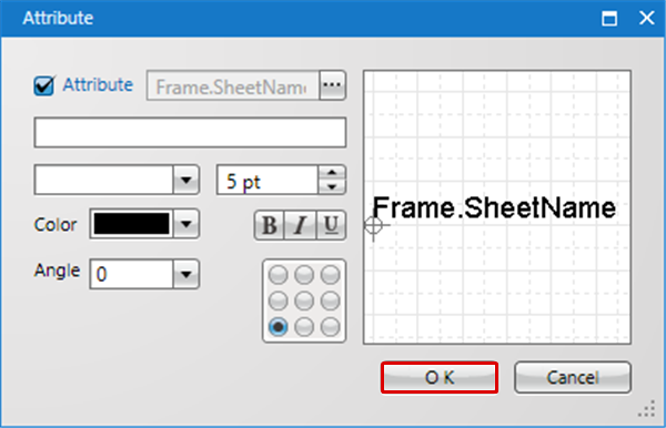
Drawing an Attribute
After selecting the Attribute Menu,
STEP 1: Select a Type
STEP 2: Input the character string
STEP 3: Click "OK"
STEP 4: Click the location where you want to place it
| Placing Attributes From the Place Attribute Dialog |
| Use the Place Attribute dialog to place the attribute. |
|
|
|
 |
|
 |
|
 |
|
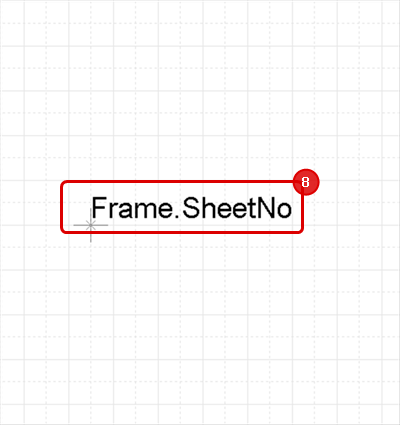 |
Rotating an Attribute
While drawing, it rotates 90 degrees.
There are the following methods for rotating.
Method 1: [Right Click] => Select [Move/Rotate/Mirror] => [Rotate]
Method 2: [Keyboard] => Press [R]
Rotate Example
| Before Rotate | After Rotate |
|
|
|
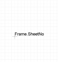
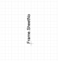
Rotation is 90 degrees to the left. There is also a Reverse Clockwise Menu.
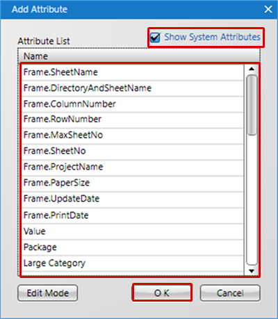
| About System Attributes |
|
System Attributes are attributes prepared by the system in advance. |
|
|
||
|
 |
|
 |
|
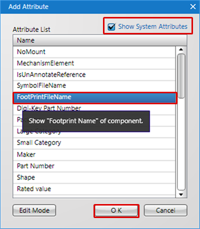 |
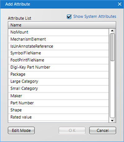
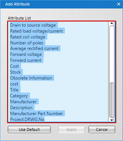
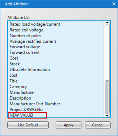
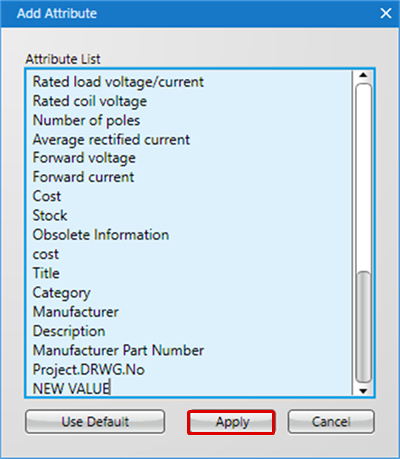
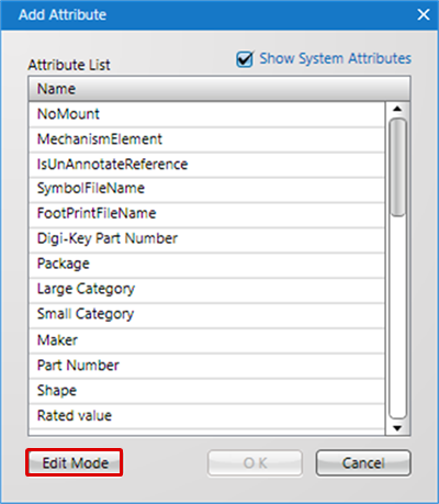
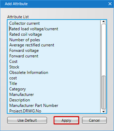
| Adding/Editing Attributes |
| The following will explain how to add and edit an arbitrary attribute. |
|
 |
|
 |
|
 |
|
 |
| Deleting an Attribute |
| The following will explain how to delete an unnecessary attribute. |
|
 |
|
 |
|
 |
Exiting Attribute Mode
The following is the operation for exiting Attribute mode.
Right click, Select => [Cancel]
* Press "Escape" on the keyboard