

PCB Layout CAD : Import/Export IDF
Exporting IDFs
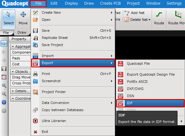
With Quadcept, IDF V3.0 format files can be exported from the PCB design screen.
IDF(Intermediate DataFormat)data isa three dimensional intermediate format between electronic board CAD and mechanical 3D CAD,
and by exporting IDF files, it is possible to collaborate with 3D CAD.
After adjusting component positions using 3D CAD, it is possible to reflect it to the component position on the PCB design drawing by reading the IDF file.
The following will explain how to export IDF files.
| Exporting IDFs |
|
The following will explain how to export an IDF file from a PCB document. |
|
 |
|
 |
|
 |
|
 |
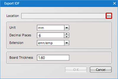
IDF Export Settings
| Item | Content | ||||||||||||||||||
|
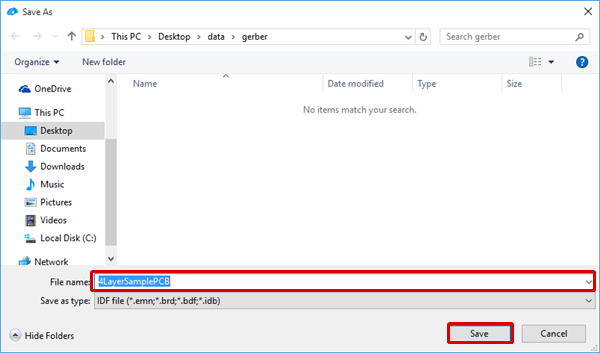
Location |
Selects the save location for the IDF export file. |
||||||||||||||||||
|
Unit |
Selects the export unit from "mm, "mil", and "inch". |
||||||||||||||||||
|
Decimal Places |
Sets the decimal places. |
||||||||||||||||||
|
Extension |
The export file extension can be set.
|
||||||||||||||||||
|
Board Thickness |
Sets the board thickness. |
Component Height is exported using the "Component Height" set in each footprint.