Configure settings for Design Instructions.
It is possible to input instructions for components and wires.
It is also possible to input instructions related to overall design.
With DRC, unconfirmed Design Instructions are detected.
For more details about opening the DRC/MRC Settings screen, refer to About DRC/MRC Settings.
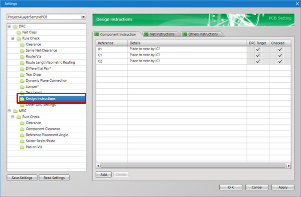
Design Instruction Types
The following are the types of Design Instructions that can be configured.
| Item |
Content |
|
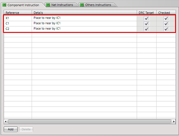
Component Instruction
|
Instructions related to components based on References can be described.
=> Ex.: "X1: Place to near by IC1", etc.
|
|
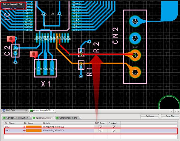
Net Instructions
|
Instructions related to Nets based on the Net Name can be described.
It is also possible to specify the Net Color.
=> Ex. "Pair routing with CLK1", etc.
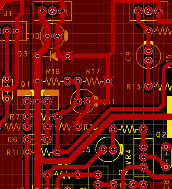
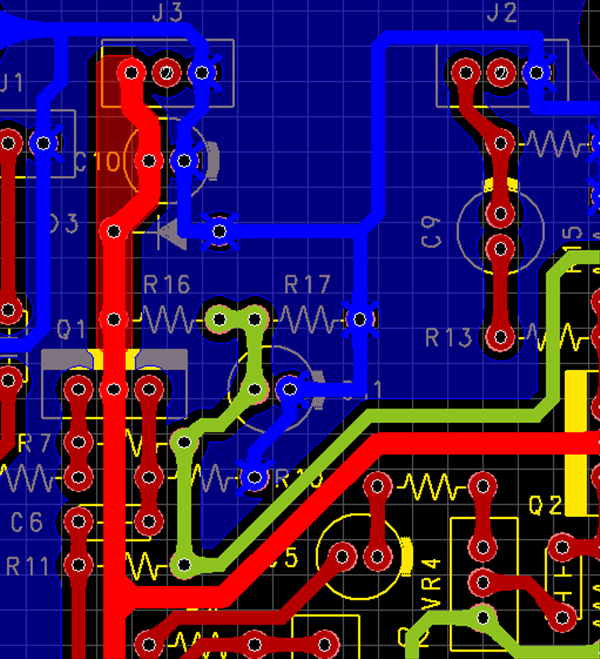
PCB Reference Example
| No Net Color (Display in Layer Color) |
Net Color is Set |
|
|
 |
|
|
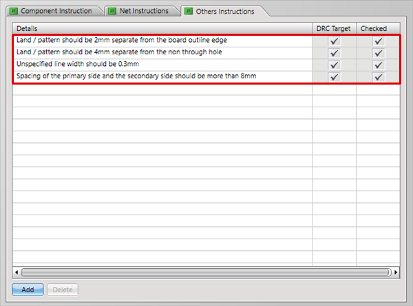
Others Instructions
|
In addition, instructions related to overall design can be described.
=> Ex. "Spacing of the primary side and the secondary side should be more than 8mm", "Unspecified line width should be 0.3mm", etc.
|
| The following will explain how to input a Component Instruction. |
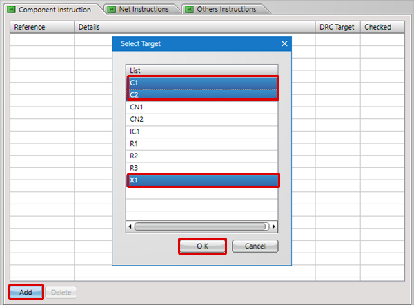
| (1) |
Click "Add".
=> The Select Target dialog opens. |
| (2) |
Select a component for which you want to input an instruction, and then click "OK".
=> Ctrl/Shift + Click allows for multiple selection.
|
|
 |
| (3) |
Input a Component Instruction in Details, and then click "OK".
|
|
 |
| (4) |
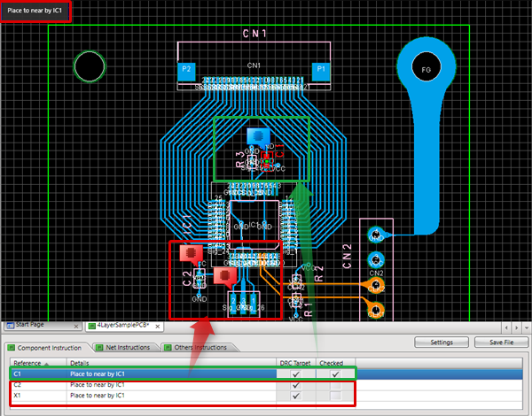
When you input a Component Instruction, a balloon will be displayed in the design drawing.
=> When a component is selected, the instruction contents will be automatically displayed at the top-left of the drawing area.
|
| |
* For Balloon Toggle Display, to toggle all,
Right click
=> [Display Options]
=> [Toggle Visibility of Balloon on Design Instruction Components].
|
|
 |
| The following will explain how to input Net Instructions. |
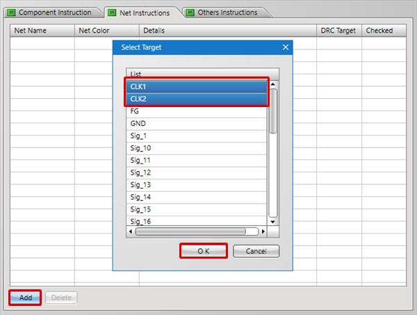
| (1) |
Click "Add".
=> The Select Target dialog opens. |
| (2) |
Select the Net Name for which you want to input an instruction, and then click "OK".
=> Ctrl/Shift + Click allows for multiple selection.
|
|
 |
| (3) |
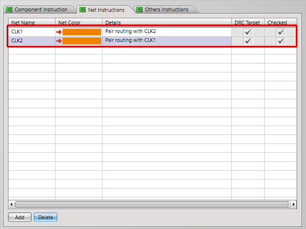
Configure Net Color individually, input Net Instructions in Details, and then click "OK".
|
|
 |
| (4) |
When you input Net Instructions, the Net Color specified for Net objects such as Routes and Planes is used for display.
=> When a Net object is selected, the instruction contents will be automatically displayed at the top-left of the drawing area.
|
| |
* For wire Toggle Display, it is possible to toggle from Right Click.
Right click
=> [Display Options]
=> [Toggle Net Color View (Route/Plane)].
Right click
=> [Display Options]
=> [Toggle Net Color View (Pad/Via)].
|
|
 |
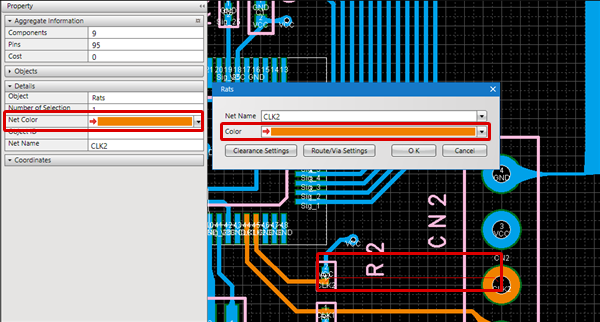
| The following will explain how to select a Net object and specify the Net Color on a PCB. |
| (1) |
Select the Net object (Rats, Wire, Plane, etc.) for which you want to set the Net Color. |
| (2) |
Set the "Net Color" in the Property Window, or set a color for "Net Color" on the Object Settings screen. |
|
 |
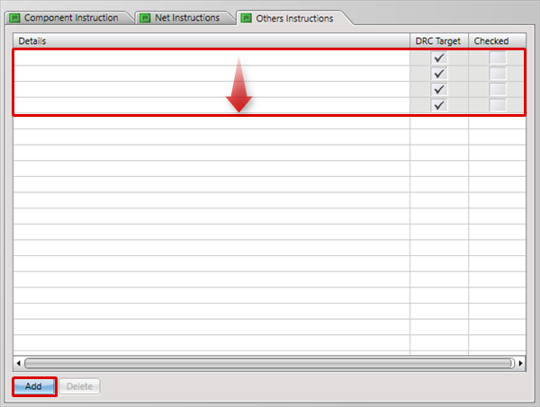
| The following will explain how to input Others Instructions. |
| (1) |
Click "Add".
=> The lines that can be input increases according to the number of clicks. |
|
 |
| (2) |
Input Others Instructions in Details, and then click "OK".
=> Input of Other Design Instructions is complete.
|
|
 |
When a check is placed for "DRC Target", it is confirmed in DRC whether a check is placed for "Checked".
When a check is placed for "DRC Target" but a check is not placed for "Checked", an error will occur.
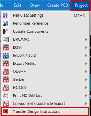
| The following will explain how to transfer Design Instructions to a schematic. |
| (1) |
Click [Project]
=> [Transfer Design Instructions].
|
|
 |
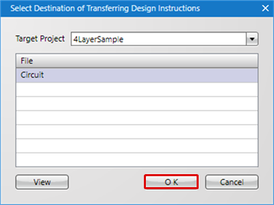
| (2) |
Select the transfer destination file for the instructions, and then click "OK".
=> When multiple Projects are registered, it is possible to switch the Target Project.
|
|
 |
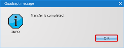
| (3) |
Transfer of instructions to the schematic data is completed.
=> While designing a schematic, you can confirm the Design Instructions in real time.
|
|
 |
It is also possible to transfer instructions from a schematic to a PCB. Therefore, after instruction contents have been confirmed, they can be reflected to the PCB.
Refer to Design Instructions in Schematic Settings.
Toggling Balloon Instruction Display ON/OFF
Using the following method, you can toggle whether or not to display balloons on the design data.
- For Balloons on Design Instruction Components
Right Click => [Display Options] => [Toggle Visibility of Balloon on Design Instruction Components].

