

Quadcept : Environment Settings
Stroke
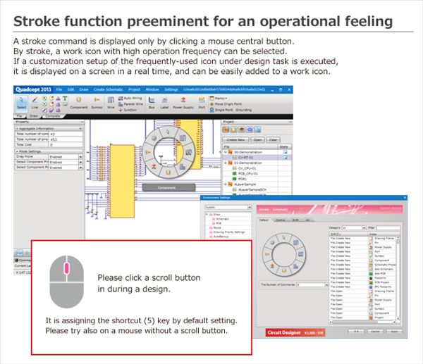
The Stroke command is an unique and convenient function found in Quadcept.
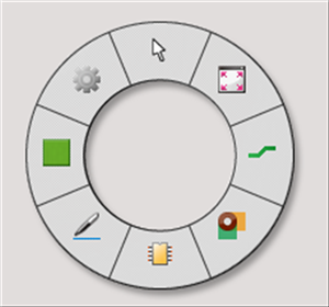
It allows you to set frequently used operation icons and display them by pressing the mouse center button.
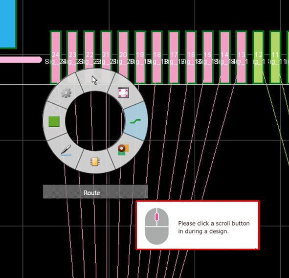
It is displayed near the cursor when you click the center button of the mouse on the design screen of a schematic, PCB, symbol, footprint, etc.
Frequently used menus can be executed without having to move the cursor very much,
which means you do not have to keep moving to mouse cursor to the Ribbon or Toolbar.
You can freely customize the menu displayed in Stroke,
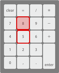
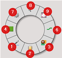
and by clicking the mouse center button while pressing the "Control" key or "Shift" key, etc. , up to 32 menus (8×4) can be registered for each document.
When settings are configured, icons can instantly be displayed while designing, and you will be able to easily select operation icons.
|
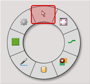
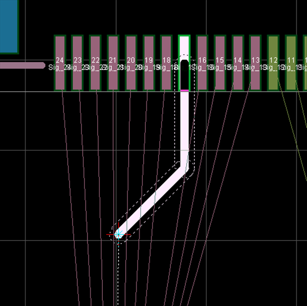
The menu is displayed near the mouse cursor, and the menu can be selected by cursor tracking.
|
* For those who want to view the video in a larger screen setting: https://youtu.be/vCcK_3QRspM
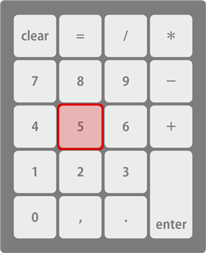
If your mouse does not have a scroll button, operation can be done using the keyboard.
By default at installation, "5" on the number pad is assigned as the Shortcut Key.
| Executing the Stroke Menu from the Number Pad |
|
|
|
  |
|
  |
The following will explain Stroke Menu items.
- Explanation of the Stroke Settings Screen
- Using the Stroke Menu
- Customizing the Stroke Menu
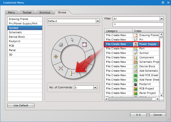
Explanation of the Stroke Settings Screen
Stroke Setting Dialog
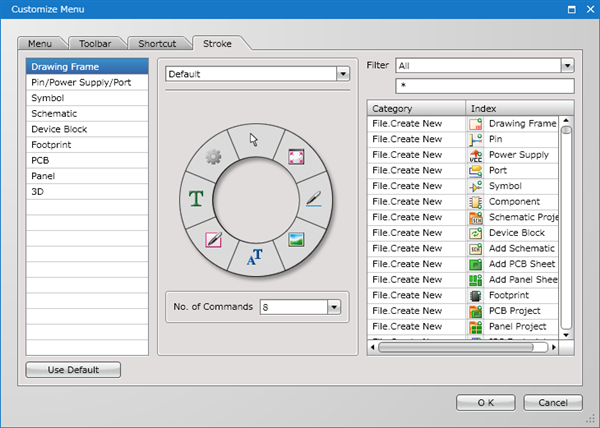
■ Document
| Document | Description |
|
Drawing Frame |
Registers the Stroke keys displayed on the create and edit screens for drawing frames. |
|
Pin/Power Supply/Port |
Registers the Stroke keys displayed on the create and edit screens for Pins, Power Supplies, and Ports. |
|
Symbol |
Registers the Stroke keys displayed on the create and edit screens for Symbols. |
|
Schematic |
Registers the Stroke keys displayed on the create and edit screens for Schematic sheets. |
|
Device Block |
Registers the Stroke keys displayed on the create and edit screens for Device Blocks. |
|
Footprint |
Registers the Stroke keys displayed on the create and edit screens for Footprints. |
|
PCB |
Registers the Stroke keys displayed on the create and edit screens for PCB sheets. |
|
Panel |
Registers the Stroke keys displayed on the create and edit screens for Panel sheets. |
|
3D |
Registers the Stroke keys displayed on the 3D display screen. |
■ Stroke
| Item | Description |
|
Default |
This is the menu displayed by pressing the mouse scroll button. |
|
Control |
This is the menu displayed by pressing the mouse scroll button while pressing the Control key on the keyboard. |
|
Shift |
This is the menu displayed by pressing the mouse scroll button while pressing the Shift key on the keyboard. |
|
Alt |
This is the menu displayed by pressing the mouse scroll button while pressing the Alt key on the keyboard. |
■ Settings
| Item | Description |
|
No. of Commands |
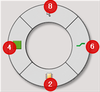
The division of registerable commands can be configured (4 parts or 8 parts). |
|
Filter |
Selecting a category from a pull-down list permits you to narrow down the items according to the selected category. |
| Using the Stroke Menu |
| The stroke menu is displayed by pressing the center mouse button on an open active document. |
|
 |
|
 |
| Customizing the Stroke Menu |
| The following will explain how to customize the stroke menu. |
|
 |