

PCB Layout CAD : DRC/MRC Settings
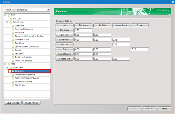
Clearance (MRC)
Execute a check for the Clearance (Interval) between each object during the MRC check.
You can check Clearance Violations between objects such as "Routes", "Vias", and "Pads" according to the Layer and Net.
For more details about opening the DRC/MRC Settings screen, refer to About DRC/MRC Settings.
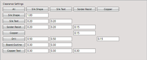
Example Clearance Settings
Settings
Configure the Clearance setting.
| Configuring Clearance Settings |
| Configures actual settings. |
|
 |
|
 |
|
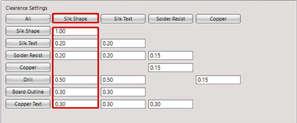 |
Clearance Settings
Specify the Clearance between objects when designing.
Example Clearance Settings

Explanation of Clearance Settings Contents
| Item Name | Content |
|
All |
By clicking "All", it is possible to change all Clearance values in the table together. |
|
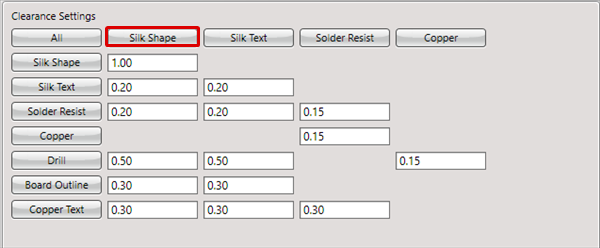
Silk Shape |
Sets the Clearance value for the Silk Shape. |
|
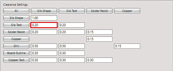
Silk Text |
Sets the Clearance value for the Silk Text. |
|
Solder Resist |
Sets the Clearance value for the Solder Resist. |
|
Copper |
Sets the Clearance value for Copper other than Copper Text. |
|
Drill |
Sets the Clearance value for Drills when there is no Land (Copper portion) in the Via/Pad. |
|
Board Outline |
Sets the Clearance value for the Board Outline. |
|
Copper Text |
Sets the Clearance value for the Copper Text. |
Input a negative number (such as -1) for items that you want place outside the check target.