Next, configure settings for the Clearance (Interval) between each object.
Settings can also be configured later, but by configuring settings in advance, design is performed while confirming the clearance width, and a Dynamic Plane Clearance shape is created automatically.
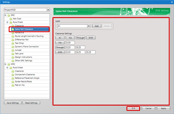
There are two types of Clearance Settings, and these can be configured from "Clearance"/"Same Net Clearance".
| (1) |
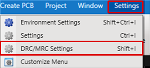
Open a PCB Document,
Select [Settings]
=> [DRC/MRC Settings]. |
|
 |
| (2) |
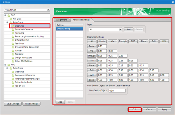
Select "Clearance".
For more details about this screen, refer to "Clearance" in PCB Setting. |
| (3) |
Configure Clearance settings from the "Assignment"/"Advanced Settings" tabs. |
| (4) |
Click "OK". |
|
 |
| (1) |
Open a PCB Document,
Select [Settings]
=> [DRC/MRC Settings]. |
|
 |