

PCB Layout CAD : Various Convenient Functions
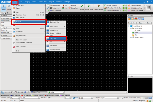
Importing DXF/DWG Files
DXF and DWG can be used for reading shape data created using other CADs.
There are various usages such as importing housing data using DXF or DWG, and making Board Outlines and Keep Out Areas.
For more details about converting imported Lines and Planes to Keep Out Areas, etc., refer to Convert to Filled Object.
Compatible Formats
The following versions are compatible DXF and DWG formats.
| Format | DXF ASCII | DXF Binary | DWG |
| Version |
R9 |
R10 |
R12 |
Compatible Documents
The following are PCB documents compatible with Import DXF/DWG.
Footprint
PCB
Panel
Importing DXF/DWG Files
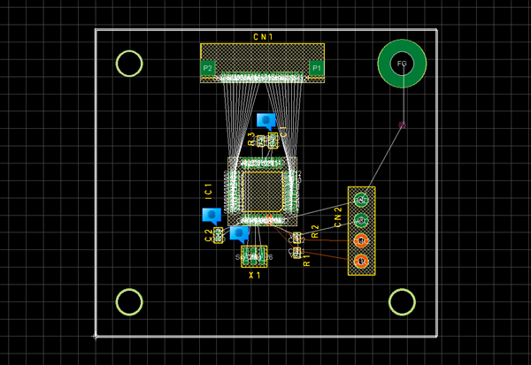
This is the method for reading housing data using DXF or DWG for making Board Outlines.
| Drawing a Board Outline by Importing a DXF/DWG File |
|
 |
|
 |
|
 |
|
 |
|
 |
There is also Create Restricted Area Automatically that automatically creates the Keep Out Area inside and outside of the Board Outline line.
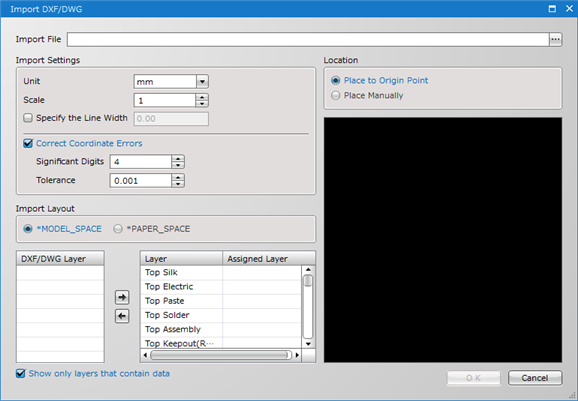
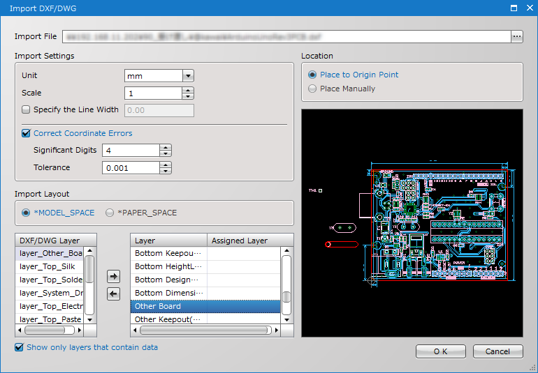
Import DXF/DWG Dialog
| Item | Description |
|
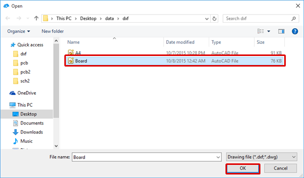
Import File |
Specifies the DXF/DWG file to be read. |
|
Unit |
Specifies the Unit for DXF/DWG import. Set the same Unit as for Export DXF/DWG. |
|
Scale |
The scale of the data (scale of enlargement/reduction) can be set when inputting DXF/DWG. |
|
Specify the Line Width |
Enable this option to specify the line width of each line included in a DXF/DWG file. |
|
Correct Coordinate Errors |
Checking the check box allows you to specify the number of digits for the coordinate values of lines, circles and arcs to be entered in DXF/DWG, and to specify tolerances for the input coordinates of objects. |
|
Import Layout |
Select "*MODEL_SPACE" or "*PAPER_SPACE" for layout block. Set the same setting as for Export DXF/DWG. |
|
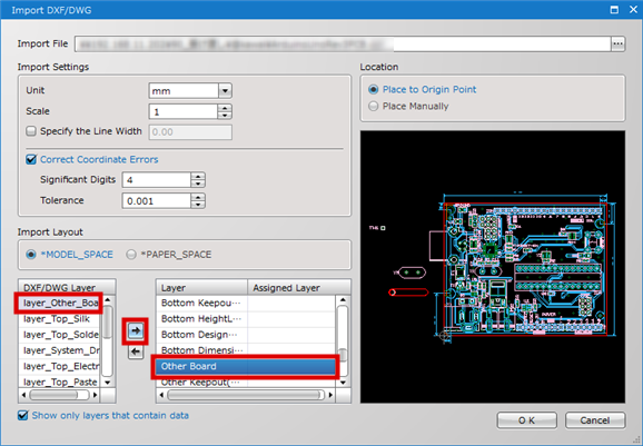
DXF/DWG Layer |
Displays the layer specified in the read DXF/DWG file as a list. |
|
Layer |
PCB sheet layers are displayed as a list. Data for the assigned layer is read to the specified layer. |
|
Assigned Layer |
The Assignment status of the DXF layer can be confirmed. |
|
Location |
Determines whether to read the imported DXF/DXG by Origin Point alignment or to read using the mouse manual placement. |