PCB Layout CAD : Create Plane
Plane Styles (Mesh)
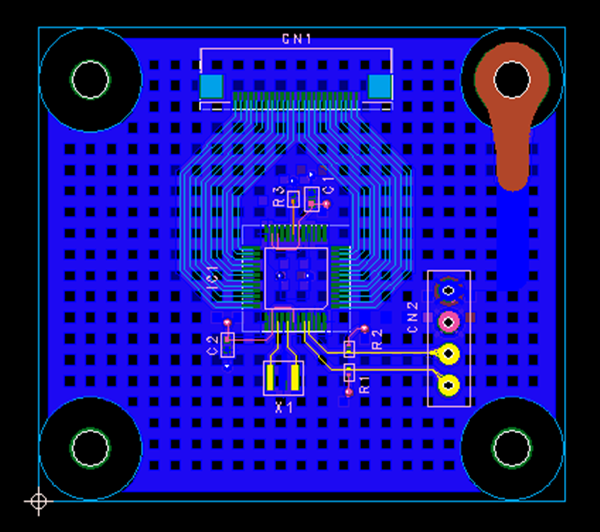
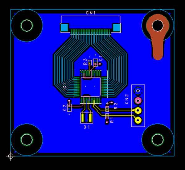
It is possible to create a "Mesh Plane" as a Plane Style.
This allows for compatibility with UL standards and transparent boards.
As Plane Styles, there are "Grid" and "Cutout", and the following will explain how to switch this style.
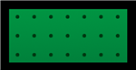
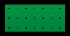
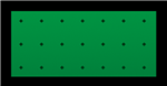
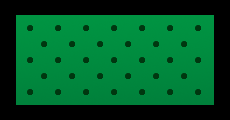
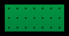
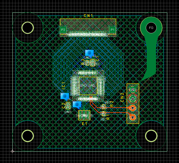
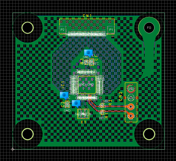
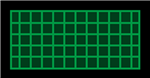
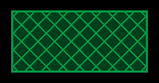
| Grid (Rhombic Lattice) | Cutout (Rectangle: Houndstooth Check) |
|
|
|
When the Style is "Cutout", for Gerber, export is done in G36, G37 (Polygon).
There are the following methods for changing the Style.
- Changing the Style from the Property Window
- Changing the Style from the Plane Screen
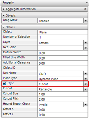
| Changing the Style from the Property Window |
| Change the Plane Style to "Grid" or "Cutout". |
|
 |
|
 |
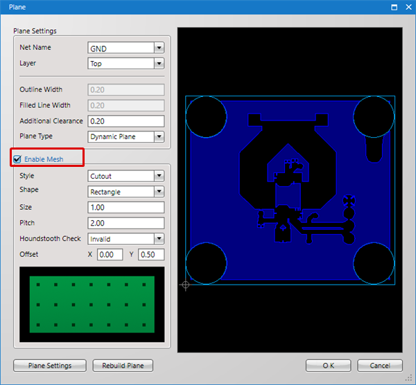
| Changing the Style from the Plane Screen |
| After placing a plane, change the Plane Style to "Grid" or "Cutout" from the Plane screen. |
|
 |
|
 |
|
|
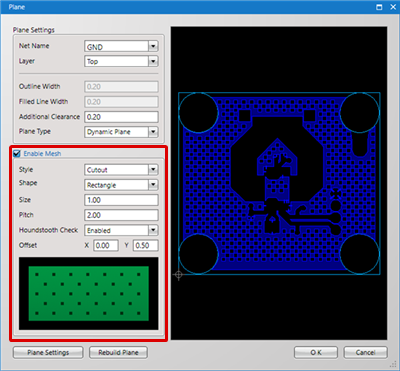
Settings when Mesh is Enabled
The following will explain each setting for when Plane Mesh is enabled.
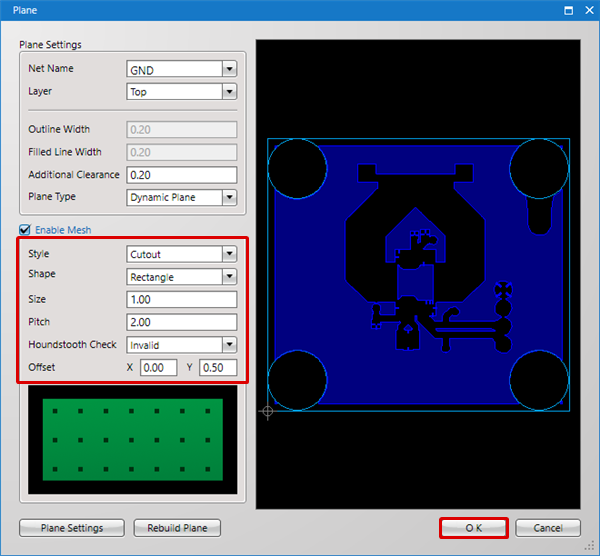
Style
| Grid Settings | Cutout Settings |
| A plane is created using Grid. For Gerber, export is done using Line Information. |
It is created by cutting out a space in the plane. For Gerber, export is done in G36, G37 (Polygon). |
|
|
|
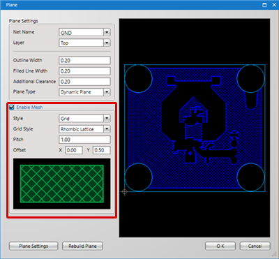
For Grid Setting
| Item | Content | ||||||||
|
Grid Style |
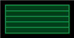
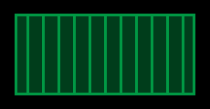
Select the Grid Style from "Horizontal", "Vertical", "Cross Stripes", and "Rhombic Lattice".
|
||||||||
|
Pitch |
Sets the numerical value for the distance (pitch) with the adjacent plane portion. |
||||||||
|
Offset |
Sets the start position for the Style in the plane. |
For Cutout Setting
| Item | Content | ||||||
|
Shape |
Sets the Cutout Shape from "Circle", "Square", and "Rhombus".
|
||||||
|
Size |
Sets the numerical value for the size of the cutout space. |
||||||
|
Pitch |
Sets the numerical value for the distance (pitch) with the adjacent plane portion. |
||||||
|
Houndstooth Check |
Select "Enabled"/"Invalid" for Houndstooth Check Cutout.
|
||||||
|
Offset |
Sets the start position for the Style in the plane. |