This page explains how to convert CR-5000 Board Designer data into Quadcept files. Footprints and PCB data can be converted to Quadcept.
For the data conversion, footprint and PCB files need to be output in ASCII format. Each ASCII file can be output by converting a footprint library (*.ftp) and board database (*.pcb) into ASCII format on a computer where CR-5000 Board Designer is installed.
* This function is an optional feature of CR-5000 Board Designer.
* Only ASCII files created in "DBUnit" can be imported to Quadcept. In order to export a file in "DBUnit", output the files without specifing a unit(such as MM).
Footprint library (*.ftp) => Footprint ASCII file (*.ftf)
Board database (*.pcb) => Board ASCII file (*.pcf)
If you have any trouble with the conversion or anything unclear, contact Quadcept support.
The following will explain how to convert a footprint ASCII file (*.ftf) and a board ASCII file (*.pcf) from CR-5000 Board Designer.
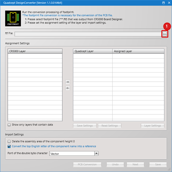
*The conversion of a footprint ASCII file (*.ftf) is necessary for the conversion of a board ASCII file (*.pcf). |
| (1) |
Click the […] button. |
|
 |
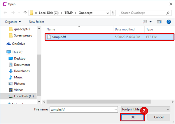
| (2) |
Select a footprint ASCII file (*.ftf) output from CR-5000 Board Designer and click the [OK] button. |
|
 |
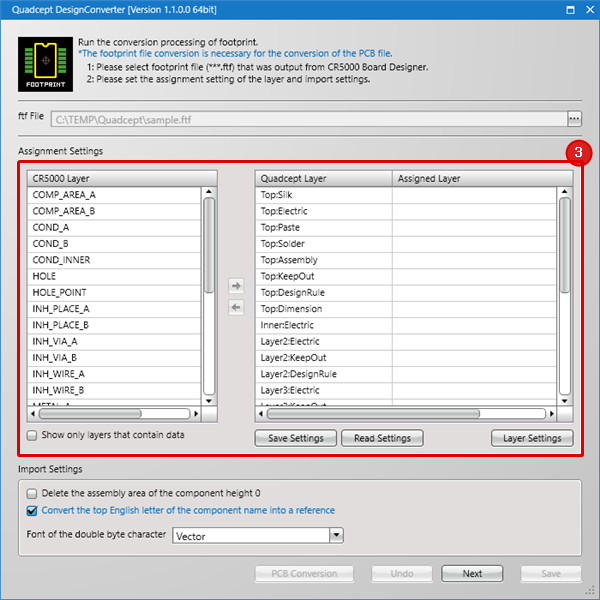
| (3) |
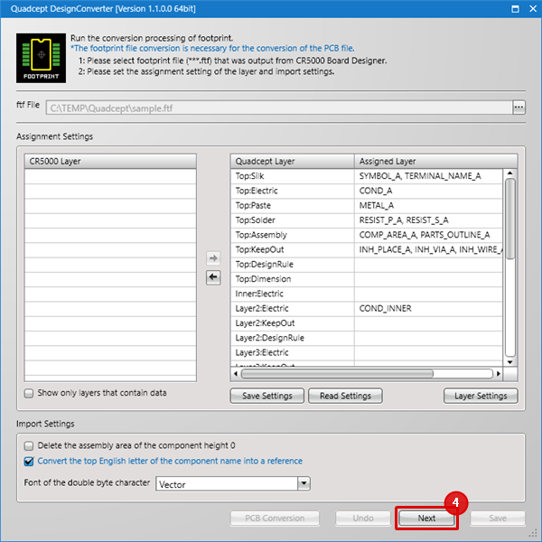
Configure the assignment settings.
Select a CR5000 layer and assign it to a Quadcept layer by using the arrow icons.
For further information, see Assignment Settings.
|
|
 |
| |
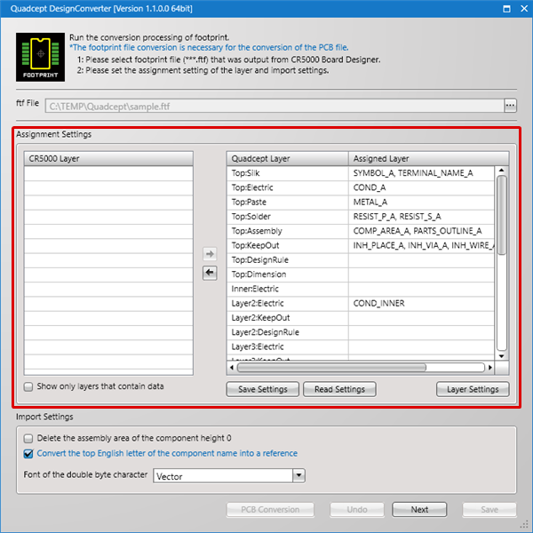
This shows that all the CR5000 layers have been assigned.
Save a file by selecting [Save Settings] when you want to save the assignment settings.
Read a file by selecting [Read Settings] when you want to read the assignment settings.
|
|
 |
| (4) |
Click the [Next] button. |
|
 |
| |
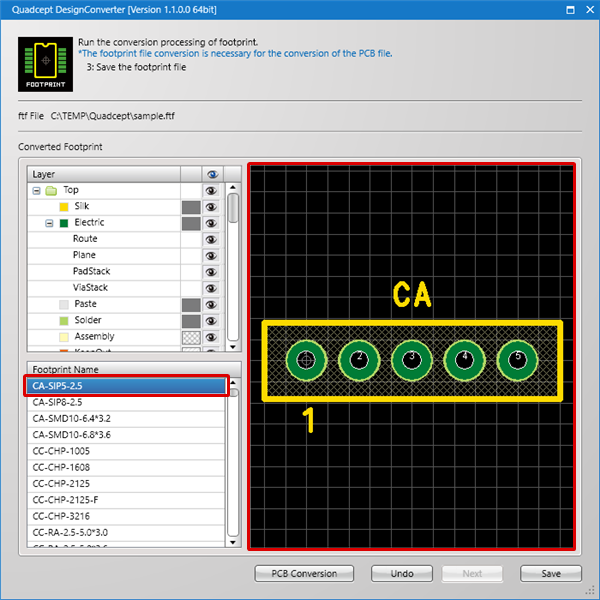
Clicking the footprint name permits you to check the state of the conversion on the preview.
The preview screen can be moved and zoomed in or out as with the Quadcept preview.
|
|
 |
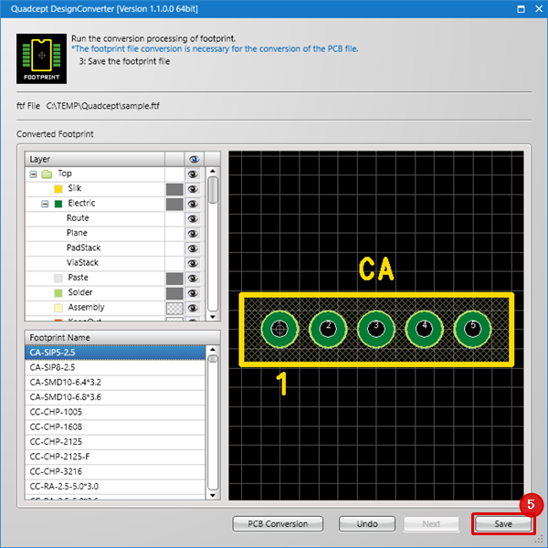
| (5) |
Click the [Save] button. |
|
 |
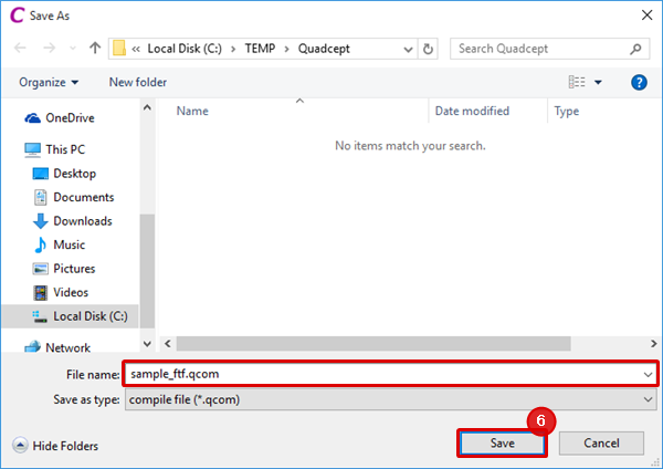
| (6) |
Enter a file name and click the [Save] button. |
|
 |
| (7) |
Click the [OK] button. |
|
 |
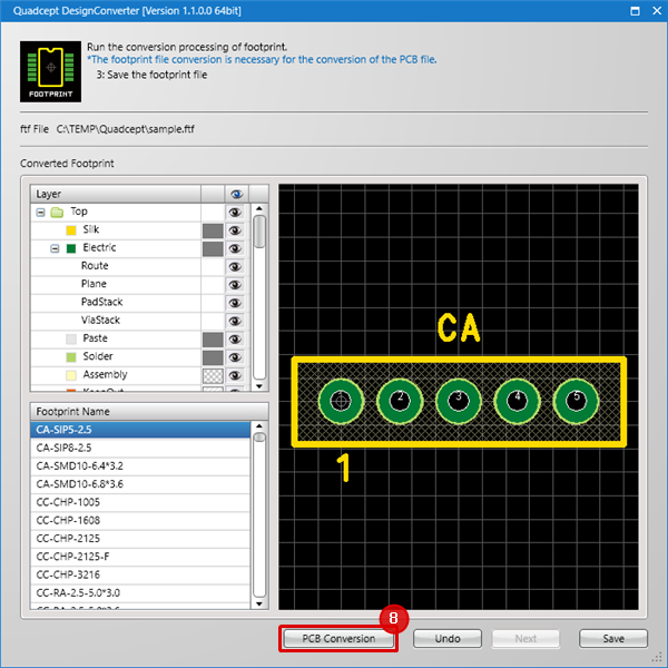
| (8) |
Run the conversion processing of PCB next.
Click the [PCB Conversion] button.
|
|
 |
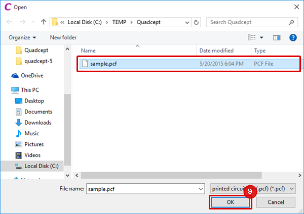
| (9) |
Select a board ASCII file (*.pcf) output from CR-5000 Board Designer and click the [OK] button. |
|
 |
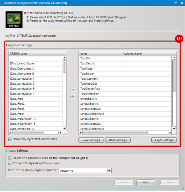
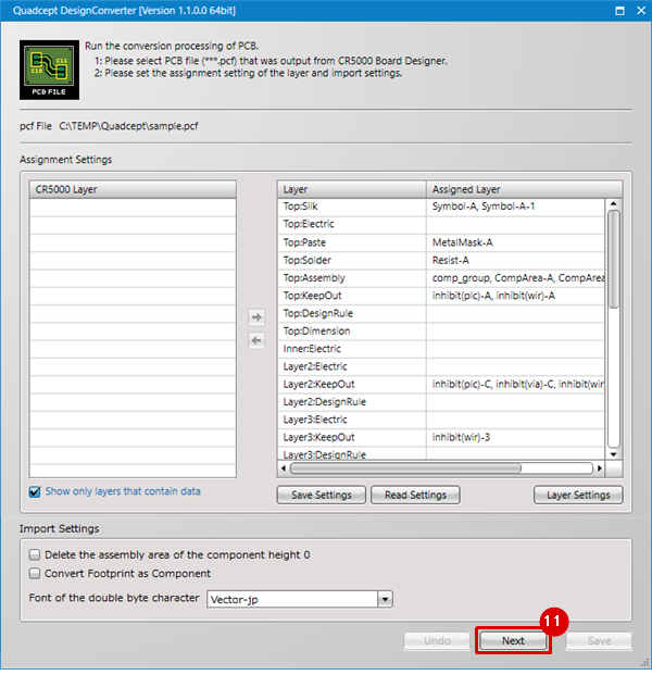
| (10) |
Configure the assignment settings.
Select a CR5000 layer and assign it to a Quadcept layer by using the arrow icons.
For further information, see Assignment Settings.
|
|
 |
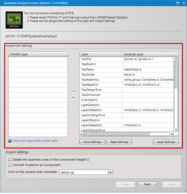
| |
This shows that all the CR5000 layers have been assigned.
Save a file by selecting [Save Settings] when you want to save the assignment settings.
Read a file by selecting [Read Settings] when you want to read the assignment settings.
|
|
 |
| (11) |
Click the [Next] button. |
|
 |
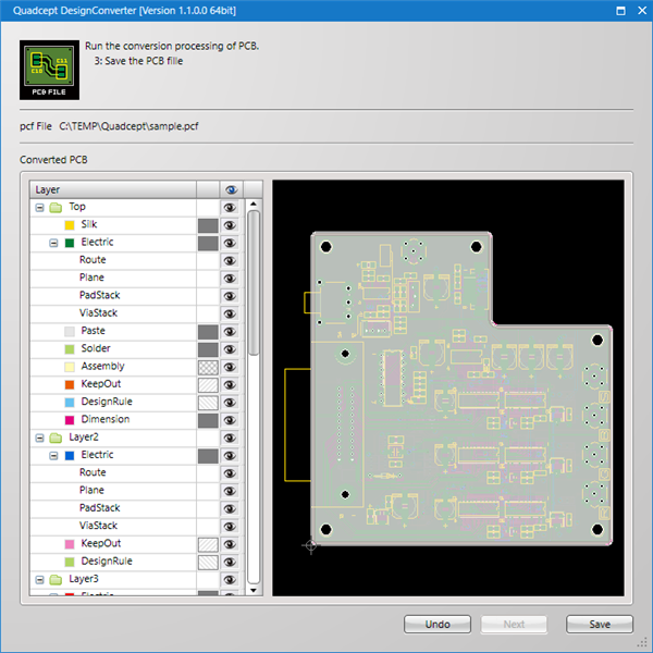
| |
The converting state of the PCB can be checked on the preview.
The layers displayed on the preview screen can be selected.
The preview screen can also be moved and zoomed in or out as with the Quadcept preview.
|
|
 |
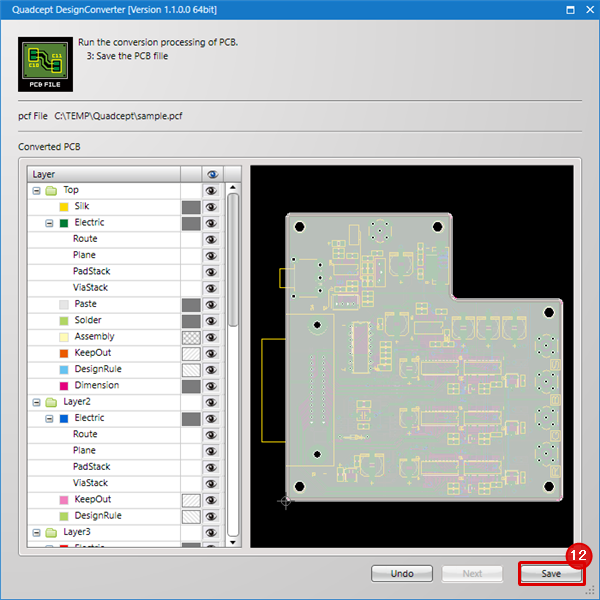
| (12) |
Click the [Save] button. |
|
 |
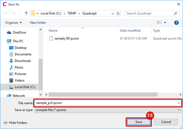
| (13) |
Enter a file name and click the [Save] button. |
|
 |
| (14) |
Click the [OK] button. |
|
 |
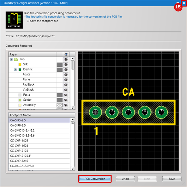
| (15) |
Click the [×] button to finish the conversion.
If you continue to convert other PCB design data, click [PCB Conversion] on the bottom left.
|
|
 |

