

Schematic Capture : Bus Wiring
Bus
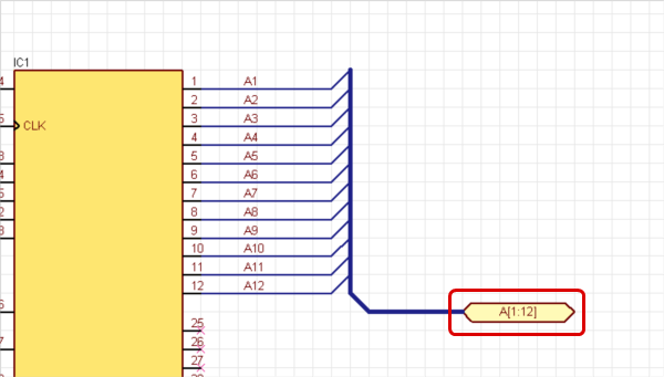
With buses, it is possible to group wires pulled from ICs, FPGAs, etc.
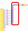
The following explains how to use buses.
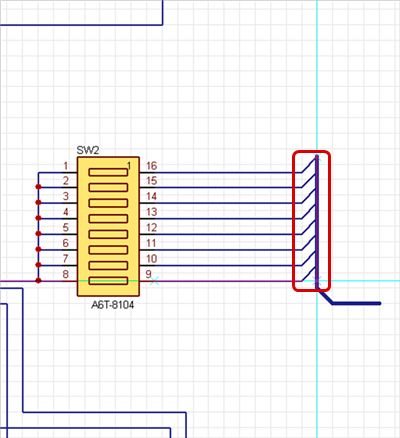
STEP 1: Create a bus.
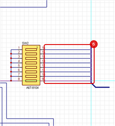
STEP 2: Connect a component and the bus with wires.
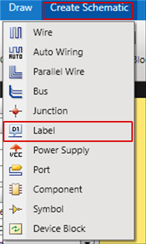
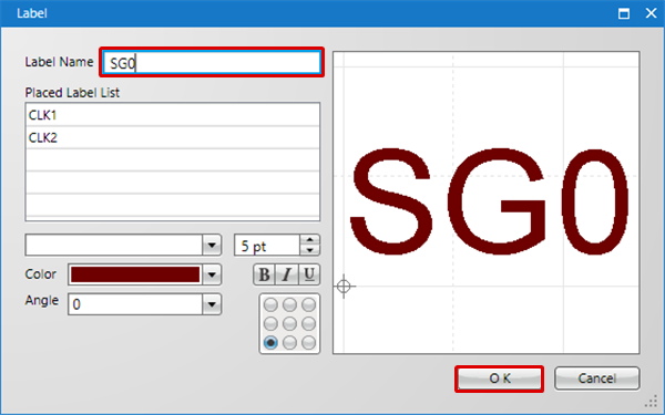
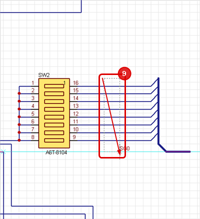
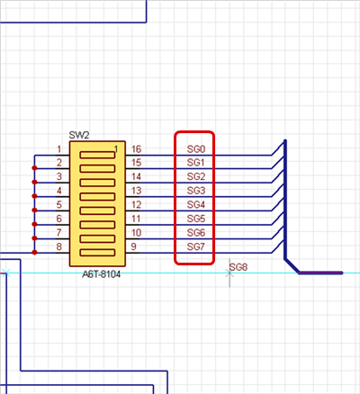
STEP 3: Place labels on the wires connected to the bus to give net names.
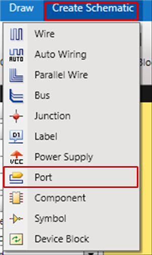
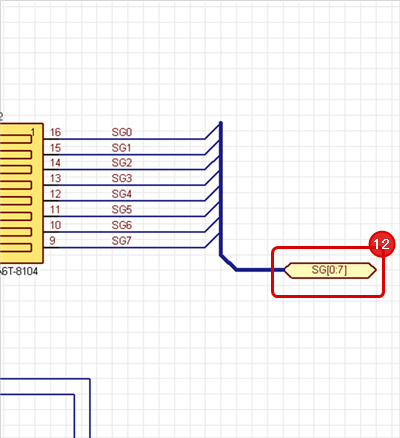
STEP 4: Connect a port to the bus.
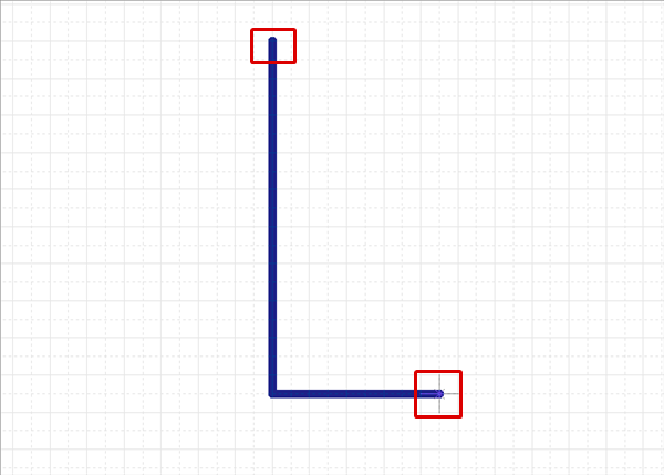
| Drawing Buses |
| The following explains how to draw buses. |
|
 |
|
 |
|
 |
|
 |
|
 |
|
 |
|
 |
|
 |
|
 |
|
 |
|
 |
|
 |
Bus Rule settings are configured after bus placement.
It is necessary to place a label to a wire connected to a bus in order to specify the Net Name.
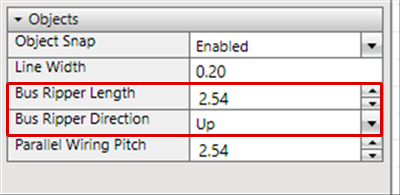
Ripper Settings
| Ripper (angled portion of the wire connected to the bus) Settings |
| When creating wires, it is possible to confirm and change settings from Property. The following explains the ripper confirmation location. |
 |
This also applies to the Bus corner.
Also, rippers are automatically created when buses are connected to each other.
| Connect buses to each other | After connection |
|
|
|
Bus Rule Settings
| Bus Rule Settings |
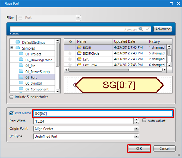
| Configure the Bus Rules for the placed buses. By configuring Bus Rules, it is possible to check whether there are insufficient labels for wires connected to a bus when running ERC. It is possible to prevent mistakes such as forgetting to connect or forgetting to place a label. To configure the Bus Rules, connect the port that imports the Bus Rules to the bus. |
 |
For more details about placing ports, refer to Placing Ports.
For more details about the Bus Rule format, refer to Bus Rule Format.
Bus Rule Format
The following explains the Bus Rule Format. The bus format consists of three parts: a label identifier, the range of label number and an operator.

Bus Rule Terms
| Term | Definition |
|
Label Identifier |
A character(s) which appears before a label number. Labels with the same name as the identifier can be connected to the bus wire. |
|
Label Number |
A number which comes after a label identifier. |
|
Range of Label Number |
The range of label number which allows connection. This is specified in the following format and labels within the range can be connected to the bus wire. |
|
Operator |
An OR operator used to specify multiple rules. It is expressed by a "/". |
Bus Rule Example
| Bus Rule | Definition |
|
DA[00:20]/D/A |
Allows connection of wires with labels from DA00 to DA20, D and A. |
Each Operation for Drawing Buses
The following explains each operation for drawing a bus.
Selecting Bus Menu
Changing Bus Corner Angle
Switching Angle
Pushback Bus
Canceling Bus
Exiting Bus Mode
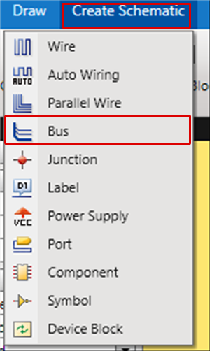
Selecting Bus Menu
Select [Create Schematic] -> [Bus]
There are several other ways to perform this. Refer to About Executing Menus.
Changing Bus Corner Angle
The bus corner angle can be changed freely.
Bus Corner Bending Angle
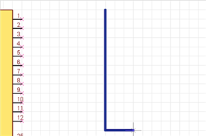
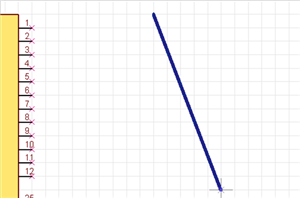
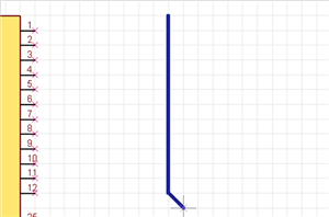
| 45 degrees | 90 degrees | Free |
|
|
 |
 |
The following is the operation for changing the bus corner bending angle.
Method 1: Right click and select [Change Bending Angle].
Method 2: Press "S" on the keyboard.
* It can also be confirmed and changed from the Property Window.
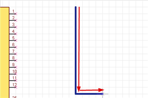
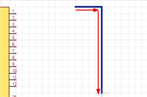
Switching Bus Angle
| Before Switching | After Switching |
|
|
 |
The following is the operation for switching the angle.
Method 1: Right click and select [Switch Angle].
Method 2: Press "X" on the keyboard.
* It can also be confirmed and changed from the Property Window.
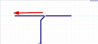
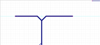
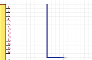
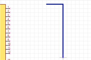
It is also possible to determine the pulling direction by tracking using the mouse pulling direction.
| When pulling to the right side first | When pulling to the bottom first |
|
|
 |
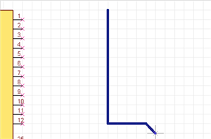
Pushback Bus
When creating a bus, you can pushback the corner to the previous status.
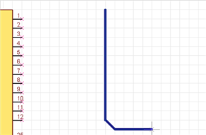
| Before Pushback | After Pushback |
|
|
 |
The following is the operation for executing pushback.
Method 1: Right click and select [Pushback].
Method 2: Press "BackSpace" on the keyboard
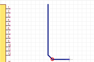
Canceling Bus
When creating a bus, it is possible to return to the status before drawing by canceling the bus being created.
| Before Canceling | After Canceling |
|
|
 |
The following is the operation for executing pushback.
Method 1: Right click and select [Cancel].
Method 2: Press "Escape" on the keyboard.
Exiting Bus Mode
The following is the operation for exiting Bus mode.
When not creating a bus,
Method 1: Right click and select [Cancel].
Method 2: Press "Escape" on the keyboard.