With Quadcept, IDF V3.0 format files can be imported to the PCB design screen.
By reading the IDF file where the Board Outline and Component Coordinates were adjusted using 3D CAD, it is possible to reflect it to the Component Coordinates on the PCB design drawing.
Component Coordinates are adjusted according to the Reference.
If there are no matching Reference components, the coordinates are not adjusted and the process is skipped.
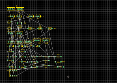
| Before IDF Import |
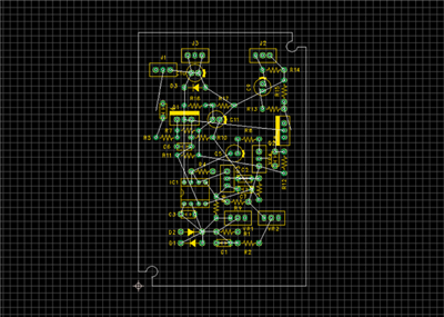
After IDF Import |
|
|
 |
| The following will explain how to import IDF files. |
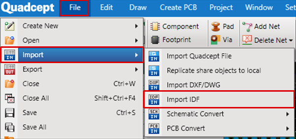
| (1) |
Select [File]
=> [Import]
=> [Import IDF]
=> The "Import IDF" screen will open. |
|
 |
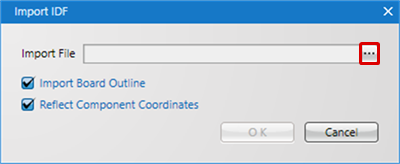
| (2) |
Click the "..." button
=> The "Open" screen will appear. |
|
 |
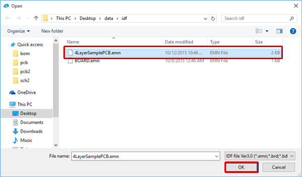
| (3) |
Select a file, and then click "Open". |
|
 |
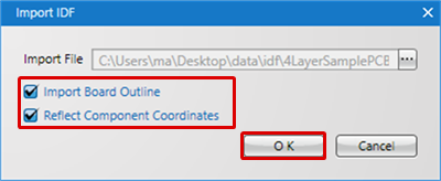
| (4) |
Configure settings and then click "OK". |
|
 |
| |
The Board Outline and Component Coordinates will be read. |
|
 |
IDF Import Settings
| Item |
Content |
|
Import Board Outline
|
Board Outline information in the IDF file is read and converted to Board Outline lines.
|
|
Reflect Component Coordinates
|
Component Coordinates in the IDF file are read, and they are reflected to components that have already been placed.
* Coordinates are reflected according to References for footprints that have already been placed.
Keep in mind that if there are no matching Reference components, the coordinates are not adjusted and the process is skipped.
|

