Configure settings for the Clearance (Interval) between each object, which is the most important item in the DRC check.
You can configure settings for Clearance Violations between objects such as a "Route", "Via", "Through", and "SMD" according to the Layer and Net.
For more details about opening the DRC/MRC Settings screen, refer to About DRC/MRC Settings.
Example Clearance Settings
Setting Method
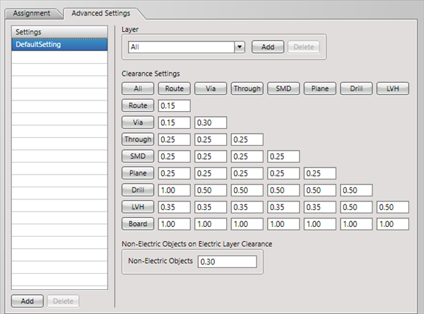
First, in Settings, there is an "Assignment" tab and "Advanced Settings" tab.
The "Advanced Settings" tab is used for configuring actual settings, and the "Assignment" tab is used for configuring which settings are assigned to which Net Class.
About the Work Procedure
STEP 1: Configure settings in the "Advanced Settings" tab
STEP 2: Assign settings to the Net Class in the "Assignment" tab
The following will explain each setting tab.
Explanation of Each Setting Tab
| Tab Name |
Content |
|
Assignment
|
It is possible to assign the "Settings" that are applied to Nets set in the "Net Class".
For example, for Net Class, you can create a "Power Supply Net Class (GND, VCC)", and assign the setting for "Power Supply Net Settings".
When it is not necessary to divide settings for each Net, all Nets apply to "DefaultClass",
so, assign the default common setting "DefaultSetting".
* All Nets not individually assigned in the Net Class are "DefaultClass".
|
|
Advanced Settings
|
Configures the actual Clearance Settings.
Multiple definition is possible for settings.
|
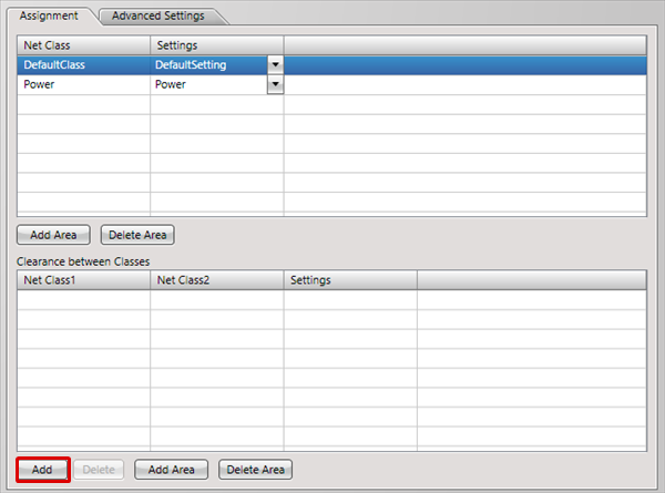
For "Clearance" settings, it is also possible to configure the "Clearance between Classes" setting.
Clearance between Classes" allows you to configure the Clearance setting between a specified Net Classes.
* When set in "Clearance between Classes", check is executed by placing higher priority on it than the Clearance set in Class.
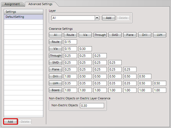
Advanced Settings
Configure the actual Clearance Settings. Multiple setting can be created, and it is also possible to configure settings by specifying the layer.

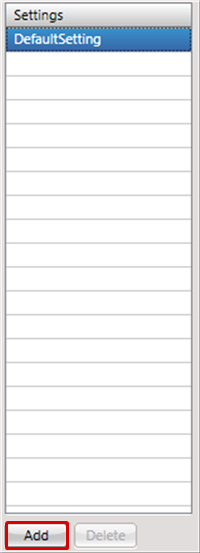
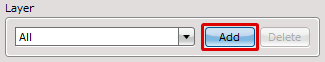
| The following will explain how to add settings. |
| |
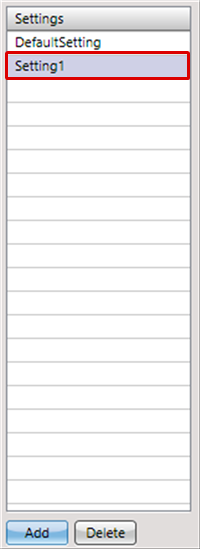
The new setting will be added. |
|
 |
| |
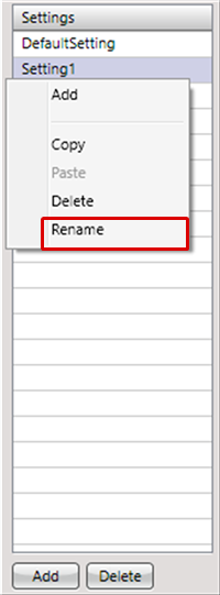
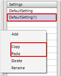
Right click
=> [Rename]. You can change the name. |
|
 |
| |
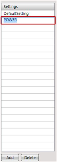
The name will be changed. |
|
 |
Settings can be duplicated by executing Copy & Paste.
This is convenient when you want to partially change a setting.
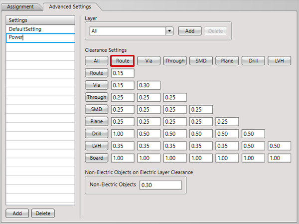
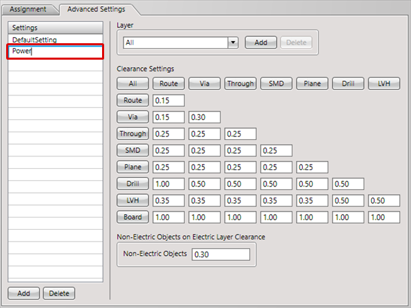
Configures actual settings.
Multiple definition is possible for settings. The following will explain how to configure settings for a Power Supply. |
| (2) |
Setting1" will be added.
* On "Setting1",
[Right Click] => [Rename].
It is possible to change the setting name.
Ex.: Set "Power" as the setting name. |
|
 |
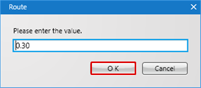
| |
The route input screen will be displayed. |
| (4) |
Set values and then click "OK". |
|
 |
| |
The same value will be set for the Vertical column. |
|
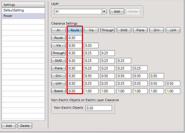 |
| |
When you want to set values individually, you can also input values to the textboxes. |
|
 |
Entering a negative value such as -1 enables to exclude the item from being checked by DRC.
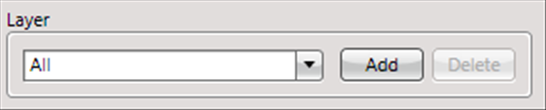
Layer Settings
Define the setting layer.
When Layer is "All", it will apply to all layers.
It is also possible to configure settings by pressing [Add] and specifying an arbitrary layer (Ex.: Top).
Specify a particular layer: Specify an arbitrary layer such as "Top", "Layer2", "Layer3", and "Bottom". Layers not specified will be set to "Other".
Ex.) When Top is added, you can configure settings separately for "All" (all layers) => "Top" (added layer), "Other" (remaining layers other than the added layer).
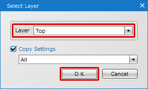
| The following will explain how to add layers (individual setting for a particular layer). |
| (2) |
Select a layer that you want to add. |
| * |
Checking the Copy Settings option enables you to copy the settings of a layer you have selected in the field under the check box. |
| (3) |
Click "OK". |
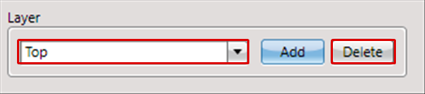
| * |
The selected layer and "Other" will be added to the Layer. "Other" means the rest of layers except the layer you have selected. |
|
 |
| The following will explain how to delete a layer. |
| (1) |
Select the layer that you want to delete. |
| (2) |
Click "Delete". |
|
 |
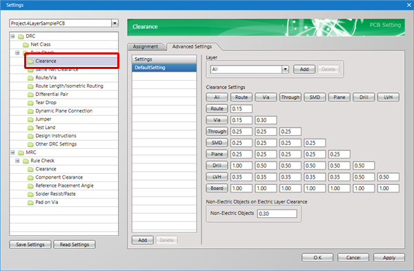
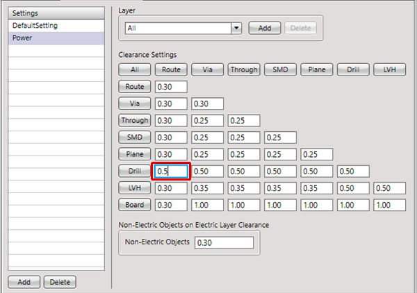
About Clearance Settings
Specify the Clearance between objects when designing.
Errors and Warnings are detected by executing a check using this Clearance value while running the DRC.
The value at the intersection of the vertical and horizontal axes applies as the Clearance setting. In the figure below, the setting is the Clearance values for SMD and Through.
Example Clearance Settings
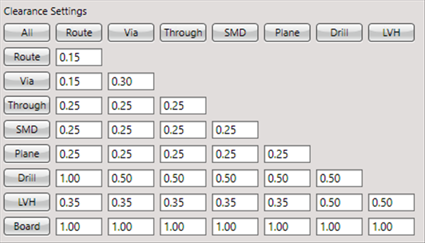
Explanation of Clearance Settings Contents
| Item Name |
Content |
|
All
|
By clicking "All", it is possible to change all Clearance values in the table together.
|
|
Route
|
Sets the Clearance value for Routes.
|
|
Via
|
Sets the Clearance value for Vias.
|
|
Through
|
Sets the Clearance value for Through Hole Pads.
|
|
SMD
|
Sets the Clearance value for Chip Pads.
|
|
Plane
|
Sets the Clearance value for planes such as Static Planes and Dynamic Planes.
For Dynamic Planes, the Clearance is created automatically using this value.
|
|
Drill
|
Sets the Clearance value for Pads without Land (Copper).
Ex.) Mounting holes and inner layer pads without connections
|
|
LVH
|
LVH (Landless Via Hole).
Sets the Clearance value for Vias without Land (Copper).
Ex.) Inner layer Vias without connections
|
|
Board Outline
|
Sets the Clearance value for the Board Outline (Objects in "Board" for "Other" layers).
|
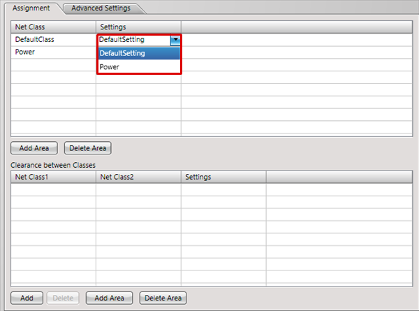
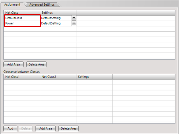
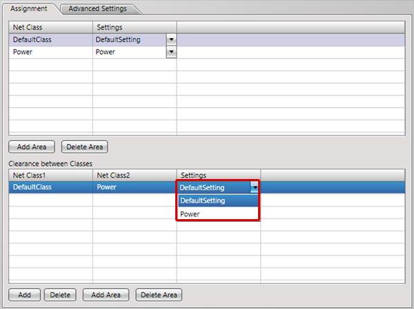
Assignment Settings
| It is possible to assign the "Settings" that are applied to Nets set in the "Net Class". |
| |
The Net Class set in the "Net Class" will be displayed. |
|
 |
| |
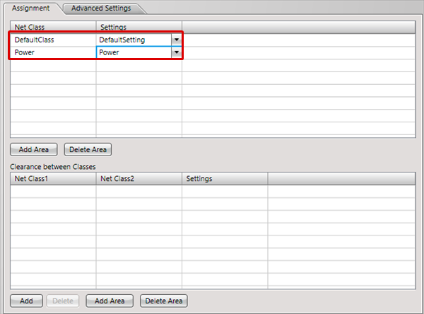
About "DefaultClass" for Net Class, refer to "DefaultSetting" in Advanced Settings,
and about "Power" for Net Class, refer to "Power" in Advanced Settings. |
|
 |
| (2) |
Select the "Net Class1" and "Net Class2", and then click "OK". |
|
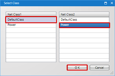 |
| (3) |
Select a Clearance between Classes setting. |
|
 |
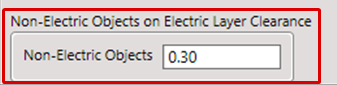
Non-Electric Objects on Electric Layer Clearance
A Non-Electric Object refers to a "Line", "Rectangle", "Circle", "Arc", "Filled Polygon", "Filled Rectangle", "Filled Circle" and "Text" object.
These objects can be placed on the Electric layer, but they cannot maintain the "Net".
This can be used for expressing etching text, copper logos, symbols, etc.
Non-Electric Objects on Electric Layer Clearance" is a function for confirming the Clearance between the above Non-Electric Objects and Electric Objects.