

PCB Layout CAD : Various Convenient Functions
Layer Drawing Order
The order in which layers are drawn on the screen is determined by the layer configuration, and the Current Layer and Layer Type settings. The physical layer and layer type set in the Current Layer and Layer Type fields are displayed on top of all other layers on the screen. The other layers are displayed according to the layer order in the layer configuration. The layer drawing order affects the object selecting order, and the object in the layer drawn on the top will be selected first.
For how to change the current layer / layer type, see here.
For details on the order in which layers are displayed, see the Layer Drawing Order section below.
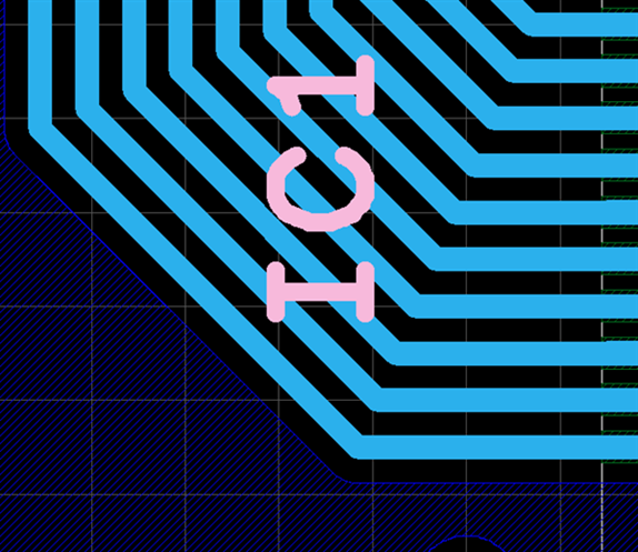
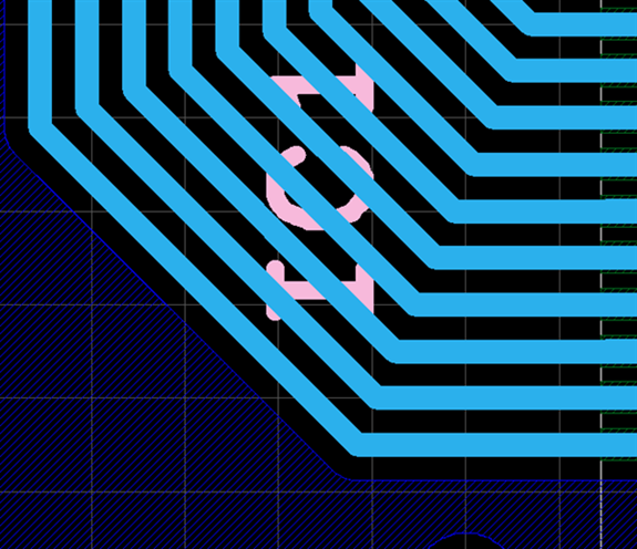
| [Current Layer]TOP [Layer Type]Silk | [Current Layer]TOP [Layer Type]Electric |
|
|
|
Layer Drawing Order
The order in which layers are drawn on the screen is as shown in the table below.
| Order | Description |
|
1 |
Current Layer / Layer Type |
|
2 |
Current Layer |
|
3 |
Layers below the current layer |
|
4 |
Object types |
| 5 |
Placed order |