PCB Layout CAD : Draw
Dimension
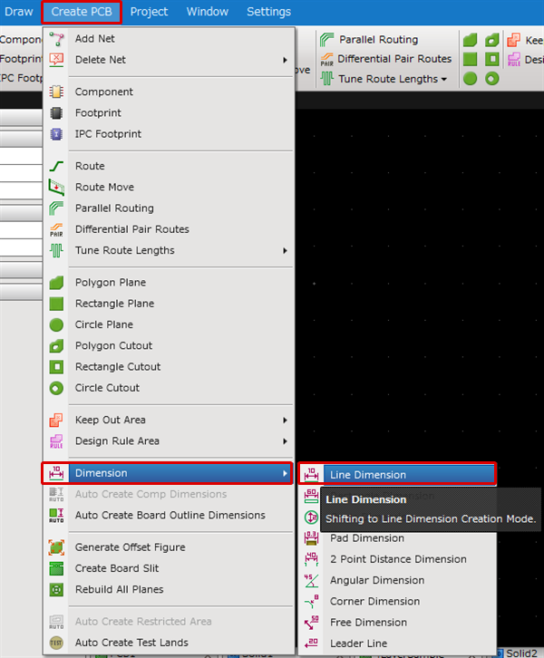
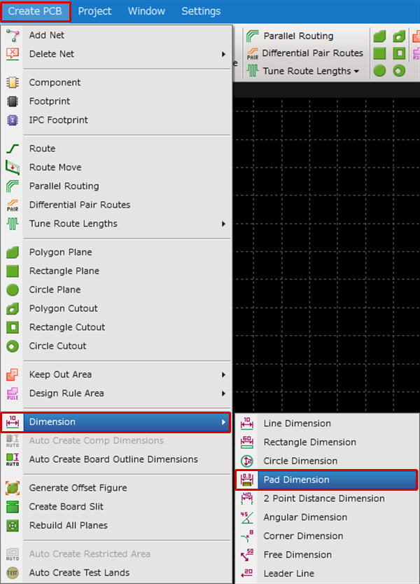
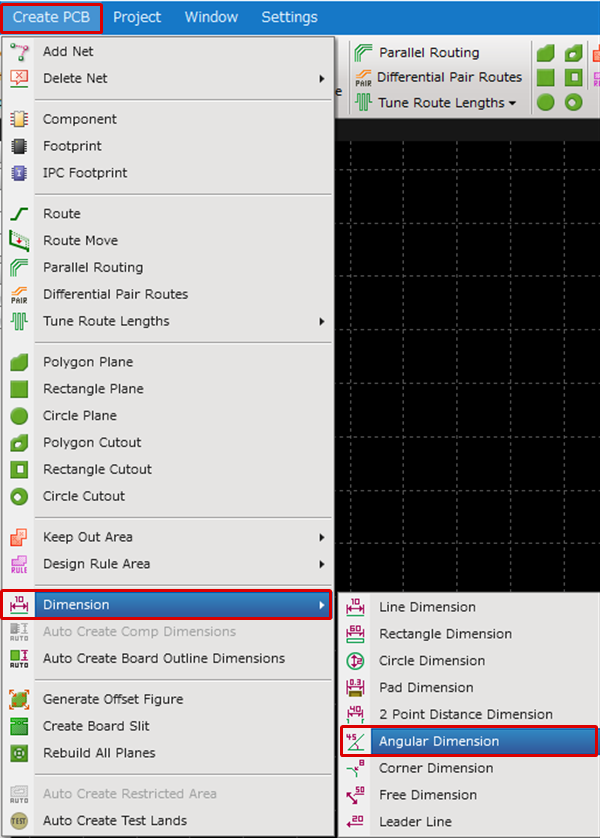
There are the following types of Dimensions.
In addition, for components, there is an auto dimension creation function for automatically creating Pad Dimensions, Assembly Dimensions, etc.
| Line Dimension | Rectangle Dimension | Circle Dimension | Pad Dimension |
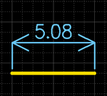
| Draws a Line Dimension. Click a line. |
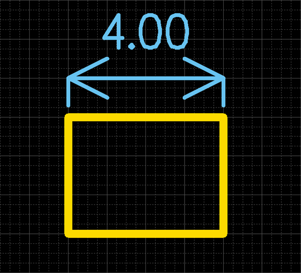
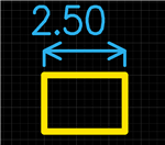
Draws a Rectangle Dimension. Click a side of a rectangle. |
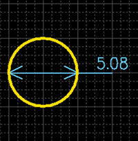
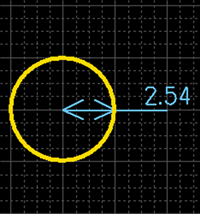
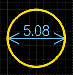
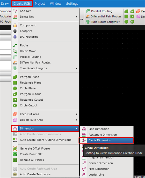
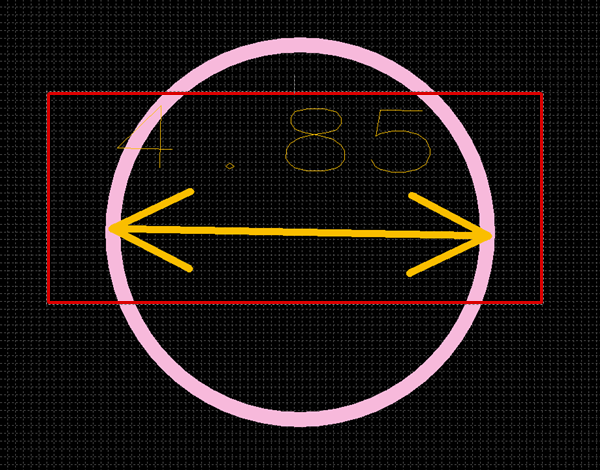
Draws the Diameter and Radius Dimension for Circles and Arcs. Click a circle. |
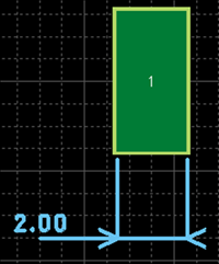
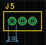
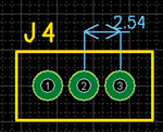
Draws the Pad Diameter Dimension. Click a pad. |
 |
 |
 |
|
| 2 Point Distance Dimension | Free Dimension | Leader Line | Angular Dimension |
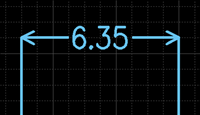
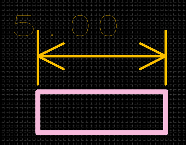
| Draws a Dimension for measuring the distance between two objects. |
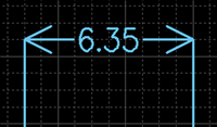
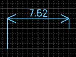
Draws a Dimension for two arbitrary coordinates. Click two points for the distance you want to measure. |
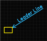
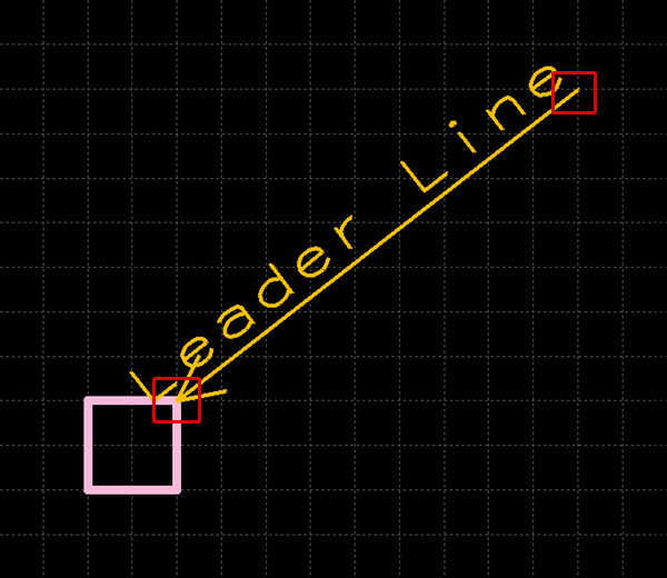
Draws a Leader Line. Click a start point and end point for the Leader Line that you want. |
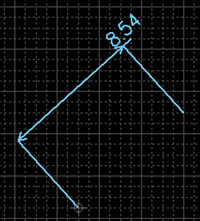
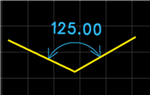
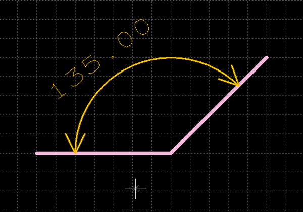
Draws a Dimension showing the Angle of two lines. Click two lines. |
 |
 |
 |
 |
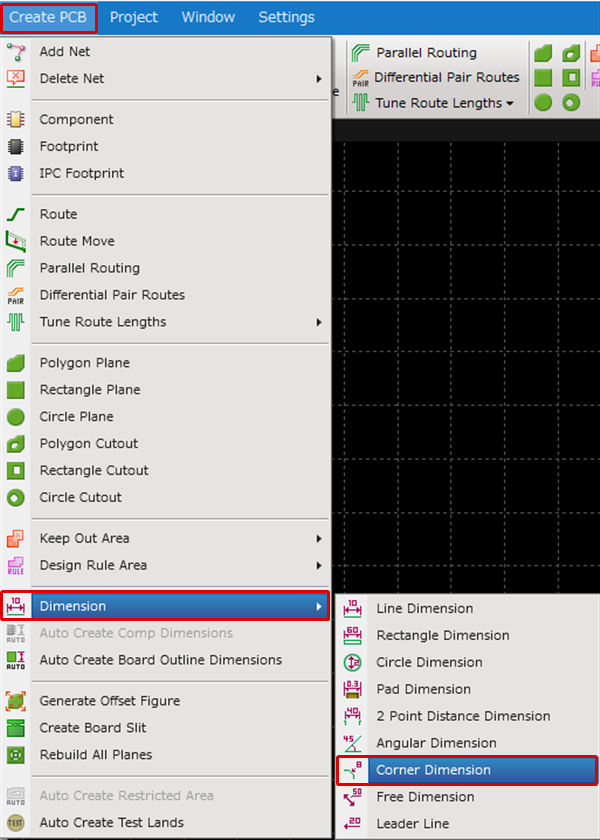
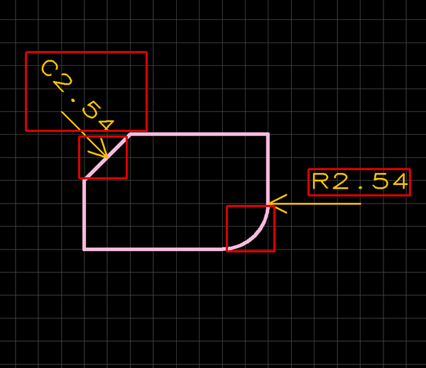
| Corner Dimension |
|
Draws a Dimension for the angle length. |
 |
In addition to the basic dimensions explained here, confirm the functions for "Create Component Dimension Automatically", which executes auto creation based on the Component Pad and Assembly, and for "Create Board Outline Dimension Automatically", which executes auto creation based on the Board Outline.
There are several other ways to perform this. Refer to About Executing Menus.
When [Update Component/Replace Component] is executed for a dimension that was created for a component on a PCB design, the creation target will be reset and it will be deleted.
The following will explain each operation for drawing Dimensions.
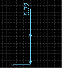
Drawing a Line Dimension
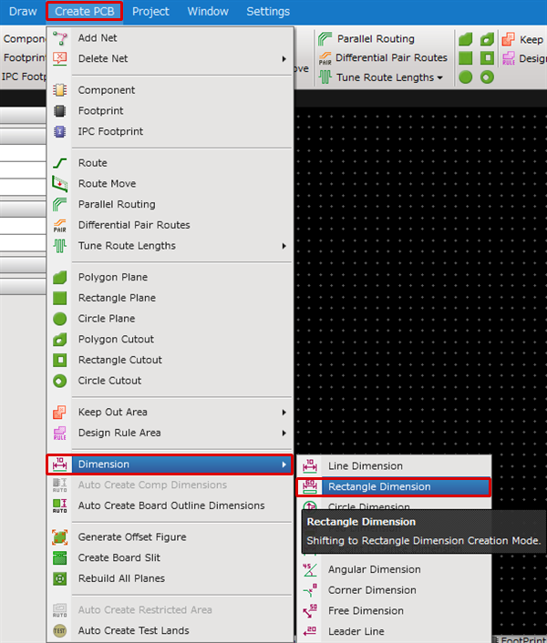
Drawing a Rectangle Dimension
Drawing a Circle Dimension
Drawing a Pad Dimension
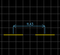
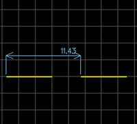
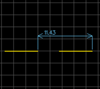
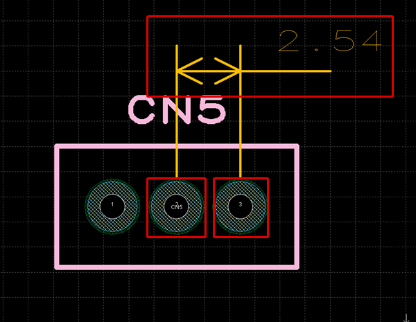
Drawing a 2 Point Distance Dimension
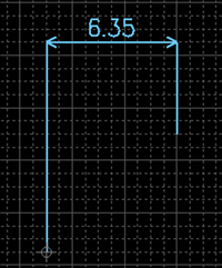
Drawing a Free Dimension
Drawing a Leader Line
Drawing a Corner Dimension
About each mode for Dimension, refer to the following.
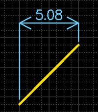
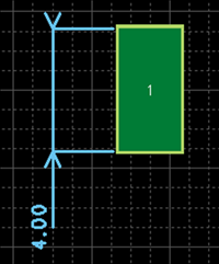
| Drawing a Line Dimension |
| The following will explain how to draw a Line Dimension. |
|
|
|
  |
|
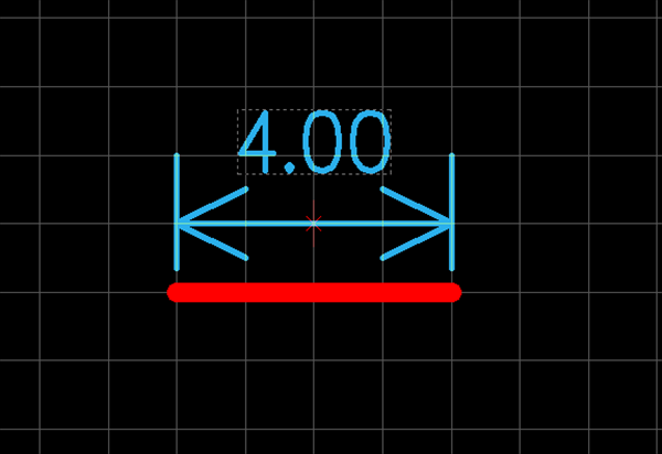 |
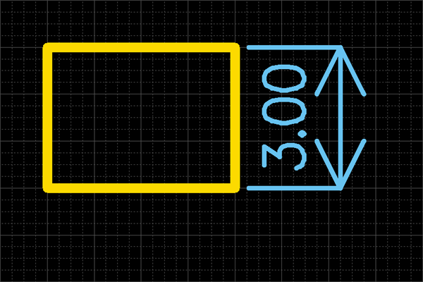
| Drawing a Rectangle Dimension |
| The following will explain how to draw a Rectangle Dimension. |
|
|
|
  |
|
 |
| Drawing a Circle Dimension |
| The following will explain how to draw a Circle Dimension. |
|
|
|
  |
|
 |
| Drawing a Pad Dimension |
| The following will explain how to draw a Pad Dimension. |
|
|
|
  |
|
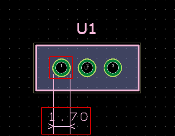 |
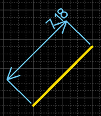
| Drawing a 2 Point Distance Dimension |
| The following will explain how to draw a 2 Point Distance Dimension. |
|
|

|
  |
|
 |
| Drawing a Free Dimension |
| The following will explain how to draw a Free Dimension. |
|
|

|
  |
|
 |
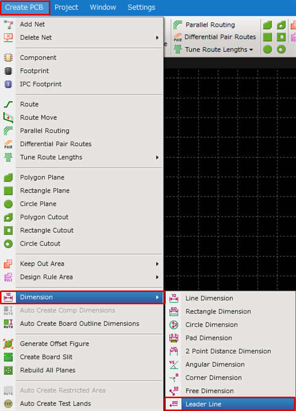
| Drawing a Leader Line |
| The following will explain how to draw a Leader Line. |
|
|
|
  |
|
 |
| Drawing a Angular Dimension |
| The following will explain how to draw an Angular Dimension. |
|
|
|
  |
|
 |
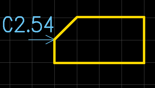
| Drawing a Corner Dimension |
| The following will explain how to draw an Corner Dimension. |
|
|
|
 |
Exiting Draw Dimension Mode
The following is the operation for exiting Draw Dimension Mode.
Right click, Select => [Cancel].
* Press "Escape" on the keyboard.
About Dimension Modes
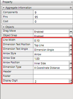
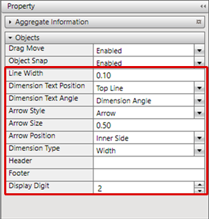
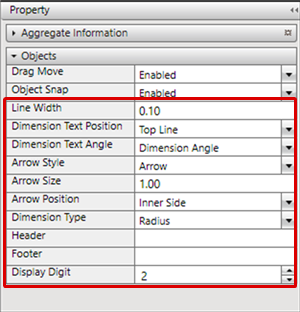
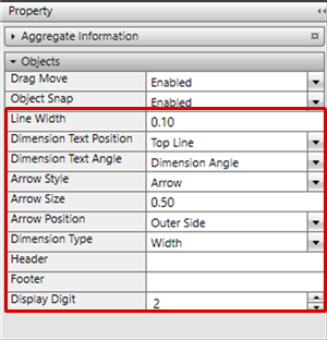
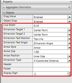
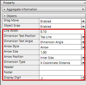
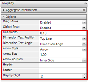
Display Settings
| Item | Content |
|
Display Digit |
Sets the Display Digit for the decimal places. Fractions are rounded off. |
|
Zero Suppression |
Use this field to determine whether trailing zeros should be suppressed or not. Use the drop-down list to choose from the following: None : The dimension value will be displayed according to the number of digits set in the Display Digit field. |
|
Display Unit |
The Display Unit can be selected from "mm, "mil", or "inch". |
|
Header |
Sets the character string displayed in front of the Dimension Text. |
|
Footer |
Sets the character string displayed after the Dimension Text. |
|
Layer |
Specifies the layer for the Dimension Line and character string. |
|
Layer Type |
Specifies the Layer Type for the Dimension Line and character string. |
Font Settings
| Item | Content | ||||||
|
Text |
Specifies the text font for the Dimension Text. "Vector" is text formed by Coordinate Information and is a simple font with a small amount of data. |
||||||
|
Line Width |
Sets the font Line Width. |
||||||
|
Size |
Sets the font size. It is possible to set W (Width) and H (Height) separately. |
||||||
|
Pitch |
Sets the font Interval. |
||||||
|
Angle |
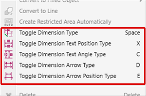
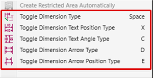
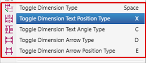
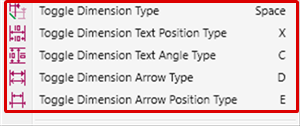
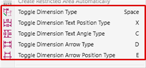
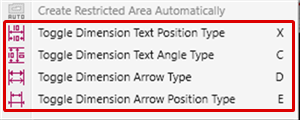
Sets the font Angle. When drawing dimensions, you can edit by right-clicking and selecting [Toggle Dimension Text Angle Type]. |
||||||
|
Text Position |
Sets the font Position. While drawing a Dimension, change by right-click and selecting [Toggle Dimension Text Position Type].
|


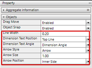
Dimension
| Item | Content | ||||||||||||||||||||||||||||||||||||
|
Line Width |
Sets the Dimension Line Width. |
||||||||||||||||||||||||||||||||||||
|
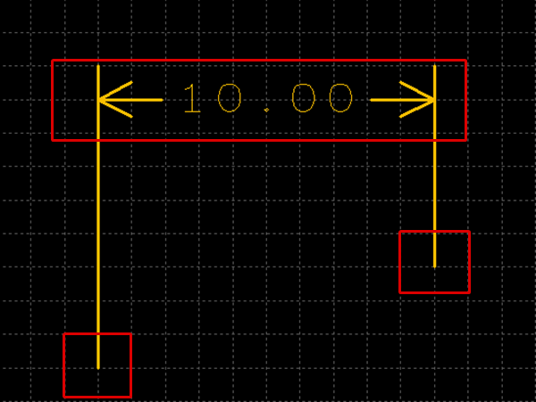
Dimension Type |
Sets the Dimension Type. While drawing a Dimension, change by right-click and selecting [Toggle Dimension Type]. ■ Line Dimension
■ Rectangle Dimension
■ Circle Dimension
■ Pad Dimension
■ 2 Point Distance Dimension ● For a Pad
● For Drawing a Line, etc.
■ Free Dimension
|
||||||||||||||||||||||||||||||||||||
|
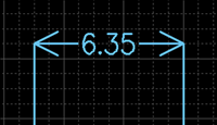
Arrow Size |
Sets the Arrow Size.
|
||||||||||||||||||||||||||||||||||||
|
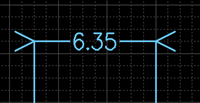
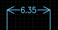
Arrow Direction |
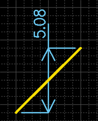
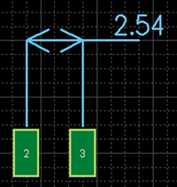
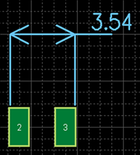
Sets the Arrow Direction. While drawing a Dimension, change by right-click and selecting [Toggle Dimension Arrow Position Type].
|
||||||||||||||||||||||||||||||||||||
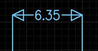
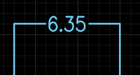
|
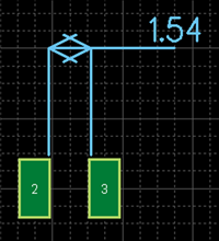
Arrow Type |
Sets the Arrow Shape. While drawing a Dimension, change by right-click and selecting [Toggle Dimension Arrow Type].
|