

PCB Layout CAD : DRC/MRC Settings
Pad on Via
Verify whether Vias exist in the SMD.
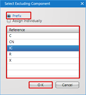
Components excluded from the check can be specified using the Reference Prefix (R, C, etc.) or the Reference (U1, C1, etc.).
For more details about opening the DRC/MRC Settings screen, refer to About DRC/MRC Settings.
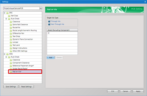
Pad on Via Settings
| Item | Content |
|
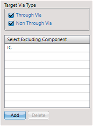
Through Via |
When this is checked, it verifies Pad overlap for Through Vias. |
|
Non Through Via |
When this is checked, it verifies Pad overlap for Non Through Vias. |
|
Select Excluding Component |
Specifies components excluded as check targets using the Reference Prefix (R, C, etc.) or the Reference (U1, C1, etc.). |
You cannot use both Reference Prefix (R, C, etc.) and Reference (U1, C1, etc.).
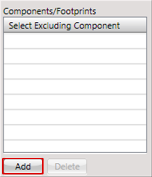
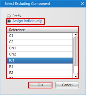
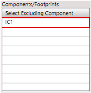
| Specifying Adding to Excluded Components |
| The following will explain how to add an excluded component specification. |
|
 |
|
|
|
 |
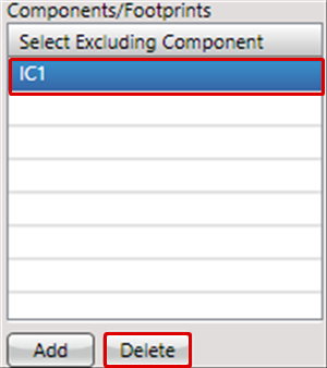
| Specifying Deletion from Excluded Components |
| The following will explain how to delete an excluded component specification. |
|
 |