

Quadcept : Creating Symbols
Creating Symbols
Create symbols (shapes) for components placed on schematics.
By creating symbols in advance, registration only needs to be done for components with the same shape, and there is the merit that it is possible to change all components that are linked at one time when the shape is changed.
Alternate Registration is possible for symbols, and it is possible to link different shapes such as positive logic symbols to negative logic symbols.
The following is the procedure for creating symbols.
STEP 1: Open the Create New screen for a symbol
STEP 2: Create a symbol shape
STEP 3: Place pins
STEP 4: Set the Origin Point
STEP 5: Configure Alternate Settings
STEP 6: Save
For more details, refer to Creation Method Flow.
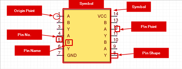
| Symbol Configuration |
|
|
Creation Method Flow
The following will explain the procedure for creating symbols.
|
STEP 1: Open the Create New screen for a symbol As the first operation, open a Create New screen for a symbol. |
↓
|
Use the draw function to draw a symbol shape. |
↓
|
Place pins at wire destinations. |
↓
|
Set the Origin Point of the symbol. |
↓
|
STEP 5: Configure Alternate Settings Alternates can be registered for symbols. |
↓
|
Save the symbol file. |