

PCB Layout CAD : PCB Settings
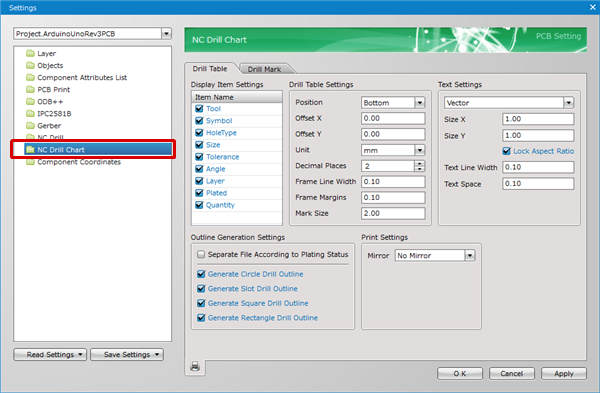
NC Drill Chart
The NC Drill Chart section of the Settings dialog allows you to configure NC Drill Chart file output settings. A NC Drill Chart file contains drilling information including positions, tool numbers, size, quantity and so on.
For more details about opening the PCB Settings screen, refer to About PCB Settings.
Sample NC Drill List
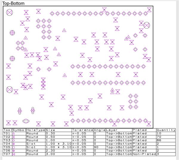
The tolerance "0.00" is also be exported in the NC drill chart.
NC Drill Chart File
NC drill chart files are created for each combination of the start layer and end layer of drills. You can also generate separate NC drill files for plated and unplated holes.
Chart Title Examples)
Top-Bottom :A NC drill chart from a Top layer to a Bottom layer
Top-2 :A NC drill chart from a Top layer to a second layer
2-3 :A NC drill chart from a second layer to a third layer
3-Bottom :A NC drill chart from a third layer to a Bottom layer
Drill Table
Display Item Settings
| Item Name | Content |
|
Tool |
Shows the Drill Tool No. (Ex.: T01, T02) |
|
Symbol |
Shows the shape of the symbol displayed on the drill position for printing. |
|
HoleType |
Shows the Drill Shape. |
|
Size |
Shows the drill size. |
|
Tolerance |
Shows the drill tolerance. |
|
Angle |
Shows the drill angle. |
|
Layer |
Shows the drill layer. |
|
Plated |
Shows the drill plating status. (Plated/Non-Plated) |
|
Quantity |
Shows the number of drills with the same size. |
Drill Table Settings
| Item Name | Content |
|
Position |
The Drill Table position can be selected from "Top", "Bottom", "Right", or "Left". |
|
Offset X |
Use this field to specify the distance by which the table should be moved along the X axis. |
|
Offset Y |
Use this field to specify the distance by which the table should be moved along the Y axis. |
|
Unit |
The unit can be selected from "mm, "mil", or "inch". |
|
Decimal Places |
The Decimal Places for Diameter can be set. |
|
Frame Line Width |
The Frame Line Width of the Drill Table can be set. |
|
Frame Margins |
The Margin width of the Drill Table and Setting Values can be set. |
|
Mark Size |
The size of the symbol displayed on the drill position can be set. |
Text Settings
| Item Name | Content |
|
Font |
The Font Type of the Drill Table can be set. |
|
Size X |
The width of text displayed in the Drill Table can be set. |
|
Size Y |
The height of text displayed in the Drill Table can be set. |
|
Lock Aspect Ratio |
By placing a check, the Vertical and Horizontal ratio of the text displayed in the Drill Table becomes fixed. |
|
Text Line Width |
The width of symbols and text displayed in the Drill Table can be set. |
|
Text Space |
The pitch (Interval) of text displayed in the Drill Table can be set. |
Outline Generation Settings
| Item Name | Content |
|
Separate File According to Plating Status |
Enable this option to generate separate NC drill chart files for plated and unplated holes. |
|
Generate Circle Drill Outline |
Enable this option to generate the outline of circle drills. |
|
Generate Slot Drill Outline |
Enable this option to generate the outline of slot drills. |
|
Generate Square Drill Outline |
Enable this option to generate the outline of square drills. |
|
Generate Rectangle Drill Outline |
Enable this option to generate the outline of rectangle drills. |
Print Settings
| Item Name | Content |
|
Mirror |
Use this control to generate a NC drill chart file with the flipped coordinate information. Use the drop-down list to choose from the following: No Mirror : A NC drill chart file is output with the viewed-from-top coordinate information. |
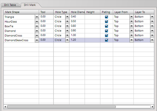
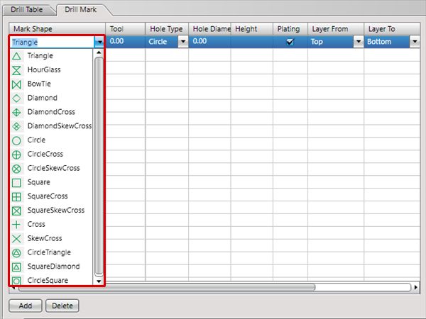
Drill Mark
The Drill Mark tab allows you to customize drilling information such as mark shapes and tool numbers shown in the NC drill chart as needed. This setting also applies when exporting NC Drill files.
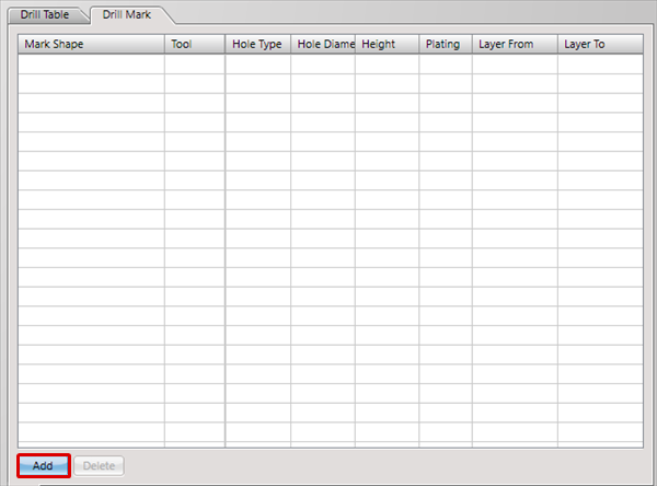
| Adding Drill Marks |
| The following will explain how to add specified Drill Marks displayed in the NC Drill List. |
|
 |
|
 |
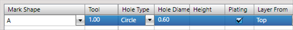
Setting Items
| Item | Shape |
|
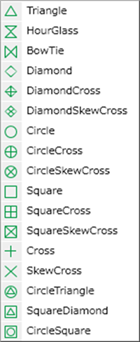
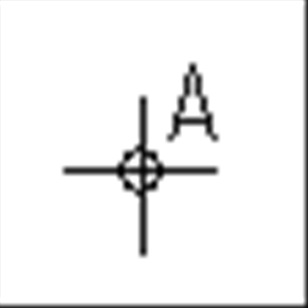
Mark Shape |
Specifies the Mark Shape for displaying the NC Drill List. By directly inputting a character string, it is possible to use a Cross and arbitrary text as a Mark. |
|
Tool |
Specifies the Drill Tool No. This setting also applies when exporting NC Drill files. |
|
Hole Type |
Sets the Hole Type that specifies the Drill Mark. |
|
Hole Diameter/Width |
Sets the hole width. |
|
Height |
Sets the hole height when the Hole Type is "Oval"/"Rectangle". |
|
Layer From |
Sets Layer From for the drill hole. |
|
Layer To |
Sets Layer To for the drill hole. |
|
+ Tolerance |
Sets the + Tolerance for the drill hole. |
|
- Tolerance |
Sets the - Tolerance for the drill hole. |
|
Angle |
Sets the Angle for the drill hole. |
|
Plating |
Sets the drill hole plating status. |
Exporting NC Drill Lists
There are the following methods for exporting NC Drill Lists.
- Click the  icon of the NC Drill List screen of the PCB Settings
- Open a PCB document, [Project] => [Print NC Drill List] => [Print NC Drill List]
- Batch Output